
Interspinous omnidirectional dynamic stabilization device

a dynamic stabilization device and interspinous technology, applied in the field of medical devices, can solve the problems of fixation failure, minor complications, and formation of pseudoarticulation or other complications, and achieve the effects of small size, strong ability of elasticity attenuation resistance, and reasonable design structur

Active Publication Date: 2020-06-30
BIODA DIAGNOSTICS WUHAN
View PDF35 Cites 2 Cited by
  • Summary
  • Abstract
  • Description
  • Claims
  • Application Information

AI Technical Summary

Benefits of technology

The present disclosure provides an interspinous omnidirectional dynamic stabilization device that overcomes defects in prior art. The device can provide maximum matching for the mobility in all directions without causing stabilizing structures to be relatively displaced, or loosen and fall off. The device has a reasonably designed structure, with a small size, is firmly fixed, and has a strong ability of elasticity attenuation resistance. The device can be easily implanted, has a strong ability of elasticity attenuation resistance, and its coronal and sagittal rotation centers are close to the rotation centers of the spine, which is beneficial for recovery of a patient from operation.

Problems solved by technology

However, many studies have shown that accelerated adjacent segment degeneration, fixation failure, pseudoarticulation formation or other complications may occur after rigid internal fixation or spinal fusion.
Among these technologies, the interspinous dynamic stabilization device may be minimally invasive during implantation, with highest safety and simplest operation, and may cause minor complications, if any.
That is, even if it fails, further surgery may not be influenced.
However, there are still many defects in the traditional interspinous dynamic stabilization device.
For example, the devices may not match the spinous anatomy, hit the spine to cause wear, or be quite complicated in structure.
And the traditional device may be too large that the wound during surgery is large and the device is difficult to install and take up much space in the body after operation.
In addition, there is a risk of disengagement when the traditional device is stabilized by an assembly, and there is a risk of loosening when the traditional device is stabilized by a binding belt.
During the installation of the traditional device, the prosthesis may be required to be close to the spinal dura mater, which increases the surgical difficulty and risk of damaging the spinal dura mater.
Further, the elastic structure in the traditional device may show poor elasticity and poor vertical support, and the traditional device has a weak ability of elasticity attenuation resistance after the operation, so it is difficult to ensure low incidence of complications and good long-term effect.
However, the part of the system to be fastened to the spinous process is a square structure which does not match the spinous anatomy of the spinous process, and in this case, the side wings should be stretched and deformed greatly with a forceps during the surgery, and the side wings should be shut together after the surgery, so the installation of such system is complicated, and the side wings are easy to be fatigue and broken.
In addition, such system may only provide sagittal extension and flexion.
However, as mentioned above, such device may only implement sagittal extension and flexion.
Such U-shaped structure shows poor vertical support.
In clinical applications of the device, the prosthesis is unable to be inserted into a depth close to the dura mater during the surgery due to the large size of the device, so the rotation center of the prosthesis is relatively far away from the rotation center of the lumbar spine when the lumbar spine is twisted, that is, when the lumbar spine moves coronal direction.
In addition, it is complicated in fixation with screws, and there is risk of the loosening of the screws.
Moreover, the lateral mobility of the device is too large, increasing a new destabilizing factor to the lumbar vertebra.
However, the previous interspinous dynamic stabilization devices are generally not able to have both good, persistent vertical distraction force and versatile mobility.

Method used


Image

  • Interspinous omnidirectional dynamic stabilization device
  • Interspinous omnidirectional dynamic stabilization device
  • Interspinous omnidirectional dynamic stabilization device

Examples


example one

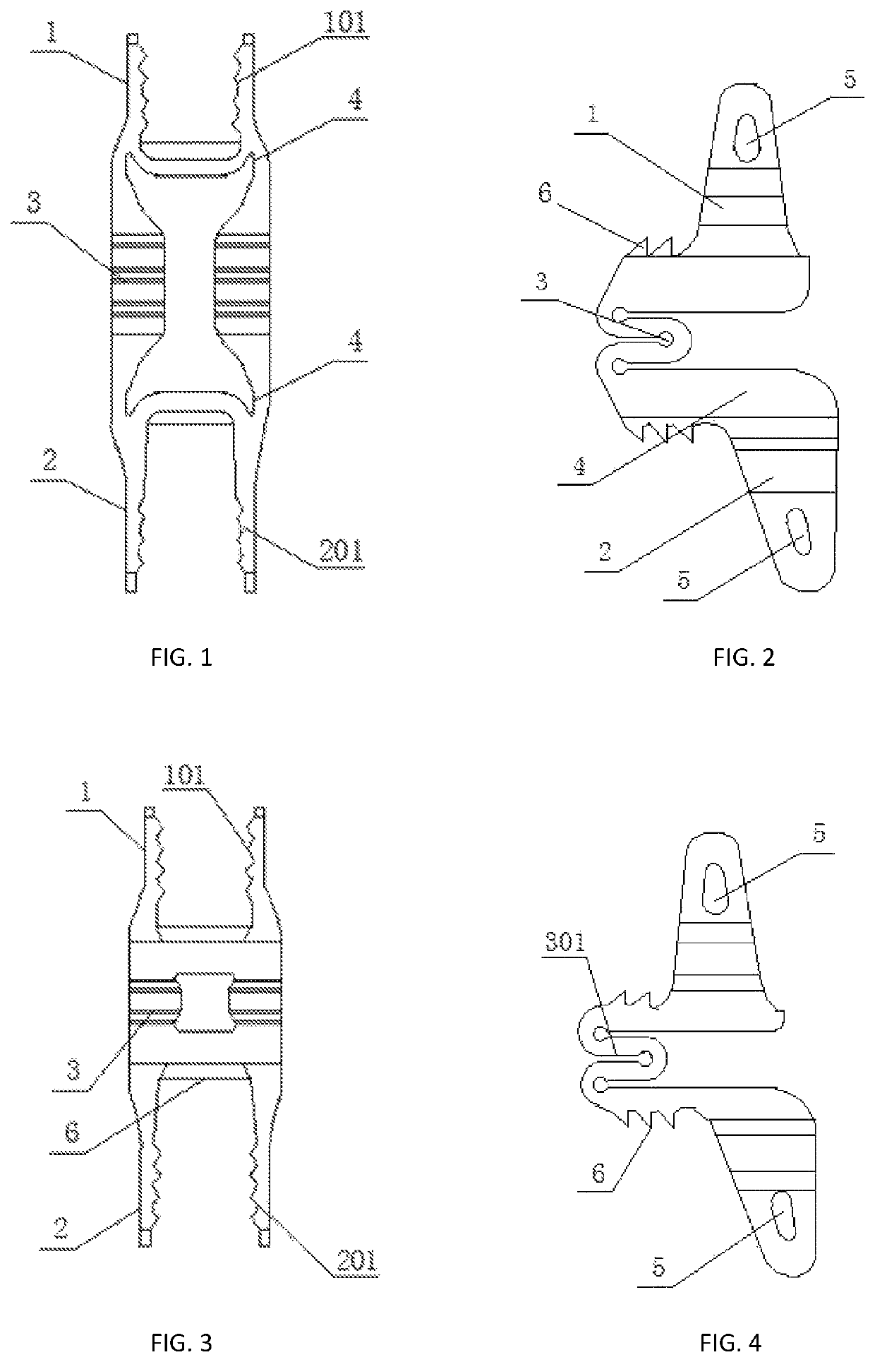
[0058]As shown in FIGS. 1-5, the interspinous omnidirectional dynamic stabilization device includes a first fixing part 1, a second fixing part 2, a connecting structure 4 and an elastic structure 3. The first fixing part 1 and the second fixing part 2 are fixedly connected to each other through the connecting structure 4 and elastic structure 3, the bottoms of the first fixing part 1 and the second fixing part 2 are provided with one or more barbs 6, the elastic structure 3 is made up of one or more U-shaped structures 301 connected to each other, and the first fixing part 1 and the second fixing part 2 are provided with fixing holes 5 respectively. The direction of the fixing hole 5 is perpendicular to or not perpendicular to an external surface of the first fixing part 1 and the second fixing part 2.

[0059]Further, both ends of an inner side of the first fixing part 1 are provided with first clamping teeth 101, both ends of an inner side of the second fixing part 2 are provided wi...

example two

[0065]In this example, the first fixing part 1 and the second fixing part 2 are connected and integrated to each other through the elastic structure 3 directly, and both the first fixing part 1 and the second fixing part 2 are flexibly removable structures.

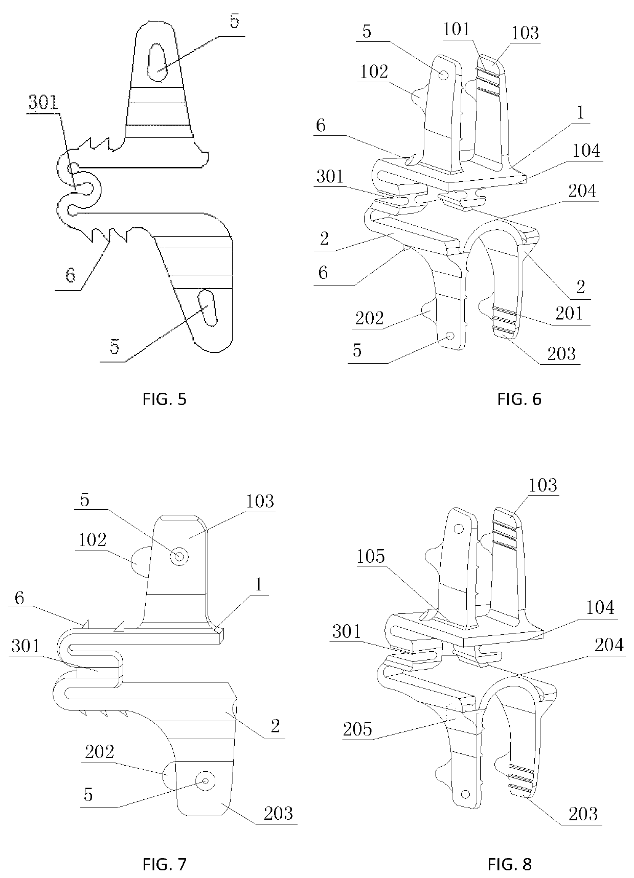
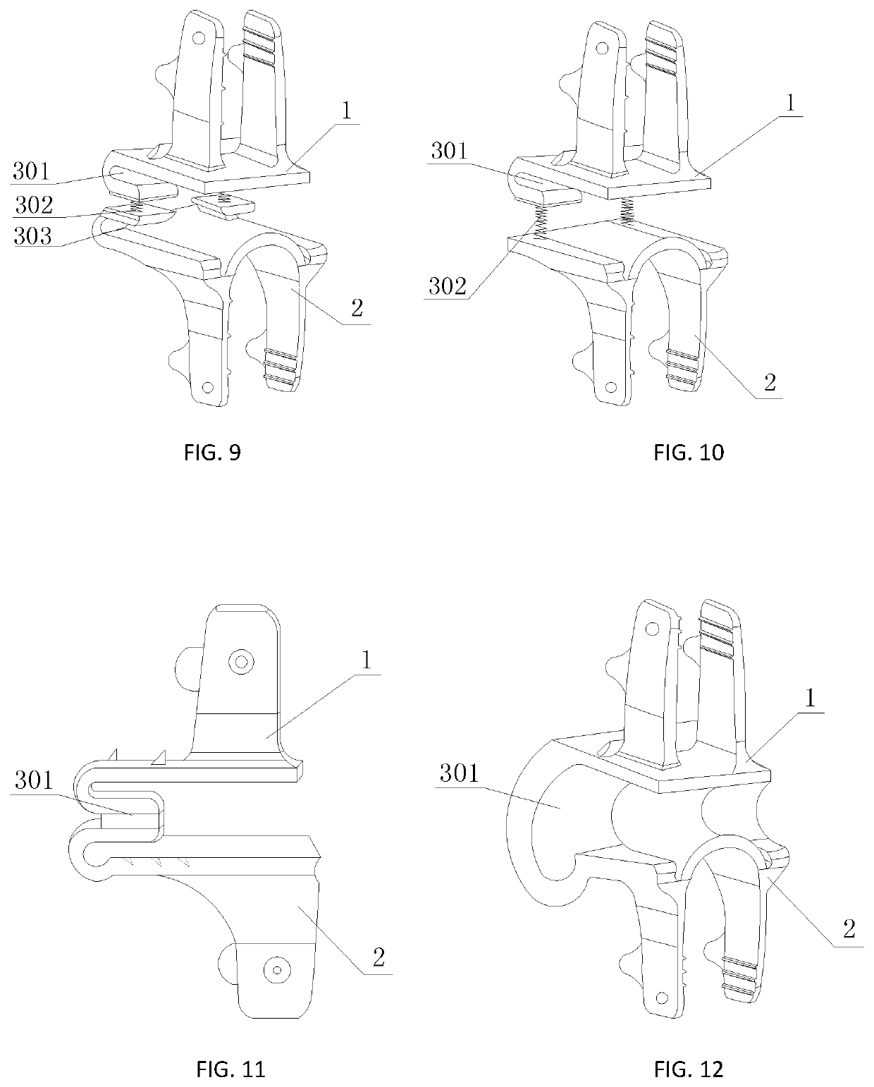
[0066]As shown in FIGS. 6-12, the interspinous omnidirectional dynamic stabilization device includes a first fixing part 1, a second fixing part 2 and an elastic structure 3. The first fixing part 1 is connected and integrated to the second fixing part 2 through the elastic structure 3 directly. Since the adjacent upper and lower spinous processes may have different dimensions and shapes, the first fixing part 1 and the second fixing part 2 may be asymmetric structures, or symmetric structures, which facilitates the matching with the sclerotin of the spinous process.

[0067]Further, as shown in FIGS. 6-8, the first fixing part 1 includes two first side wings 103, a base plate 104 and a first fastening structure 105, the two first si...

example three

[0072]In this example, the first fixing part 1 and the second fixing part 2 are two semi-U-shaped structures, and the connecting structure 4 connecting the two semi-U-shaped structures includes a holder 401 and a connecting plate 402.

[0073]As shown in FIGS. 13-25, the includes a first fixing part 1, a second fixing part 2, an elastic structure 3 and a connecting structure 4. The elastic structure 3 is arranged at the middle of the first fixing part 1 and the second fixing part 2. the first fixing part 1 and the second fixing part 2 are two semi-U-shaped structures. The first fixing part 1 is connected to the second fixing part 2 through the connecting structure 4 and the elastic structure 3. The connecting structure 4 may be strengthened by deforming the connecting structure 4 with an anti-off screw or bender after connection.

[0074]Further, the connecting structure 4 is made up of a holder 401 and a connecting plate 402, the holder 401 is arranged at the middle of the first fixing p...


PUM


Abstract

The present disclosure relates to an interspinous omnidirectional dynamic stabilization device, including a first fixing part, a second fixing part, a connecting structure and an elastic structure. The first fixing part and the second fixing part are fixedly connected to each other through the connecting structure and elastic structure. The bottoms of the first fixing part and the second fixing part are provided with one or more barbs. The elastic structure is made up of one or more U-shaped structures connected to each other. The first fixing part and the second fixing part are provided with fixing holes respectively.

Description

REFERENCE TO RELATED APPLICATIONS[0001]The application is a U.S. national phase application of international application No. PCT / CN2016 / 102584, filed on Oct. 16, 2016, which claims priority to Chinese application No. 201510681705.9, filed on Oct. 21, 2015, Chinese Application No. 201610215310.4, filed on Apr. 8, 2016, and Chinese Application No. 201610667104.7, filed on Aug. 15, 2016, the contents of all of which are incorporated herein in their entireties.FIELD OF THE INVENTION[0002]The present invention relates generally to the technical filed of implantation of a medical device into human body, and more particularly, to an interspinous omnidirectional dynamic stabilization device.BACKGROUND OF THE INVENTION[0003]At present, the spinal fusion technology has obtained a good curative effect on treating neck and waist pain, and cervical vertebra and lumbar vertebra instability, with a fusion rate above 90%. However, many studies have shown that accelerated adjacent segment degenerati...

Claims


Application Information

Patent Timeline
Patent Type & Authority Patents(United States)
IPC IPC(8): A61B17/70A61F2/44A61F2/30
CPCA61B17/7059A61F2/4425A61B17/7062A61B17/7047A61F2002/443A61F2002/30904A61F2002/30069A61F2002/30014A61F2002/30291A61F2002/30841A61F2002/30131A61F2002/30635
Inventor LI, ZHAOWENGUO, WENSHENG
Owner BIODA DIAGNOSTICS WUHAN
Learn More