
System and method for measuring junction temperature of power module

a technology of power modules and junction temperature, which is applied in the direction of power supply testing, pulse technique, instruments, etc., can solve the problem of inability to accurately predict the junction temperature, and achieve the effect of improving the junction temperature, accurately predicting the junction temperature of the power module, and improving the junction temperatur

Active Publication Date: 2020-06-30
HYUNDAI MOTOR CO LTD +1
View PDF18 Cites 1 Cited by
  • Summary
  • Abstract
  • Description
  • Claims
  • Application Information

AI Technical Summary

Benefits of technology

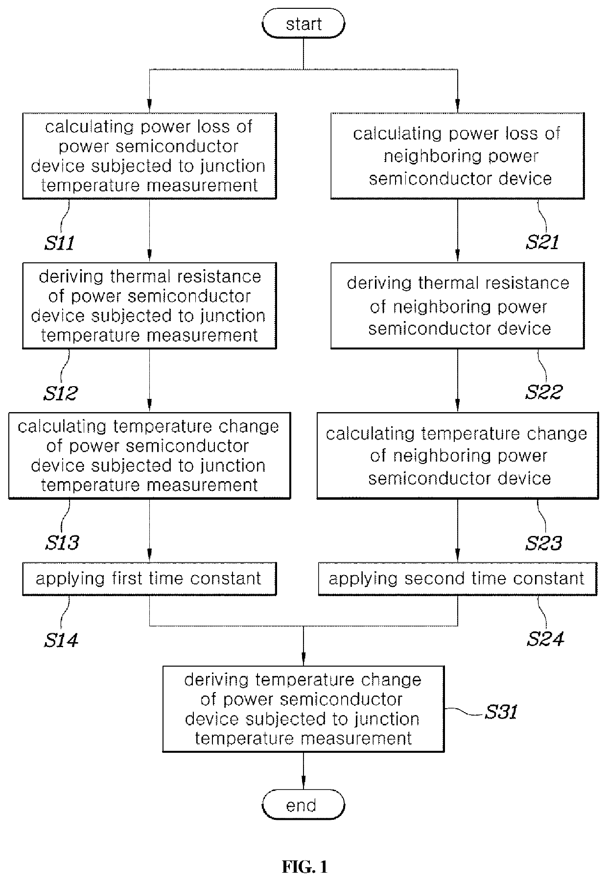
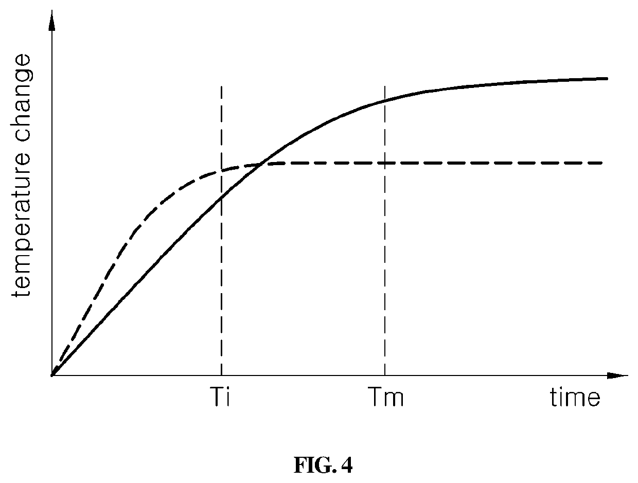
[0007]Accordingly, the present invention provides a system and method for measuring a junction temperature of a power module junction temperature. The system and method are capable of improving the accuracy of temperature measurement by more accurately applying temperature change in a junction temperature increasing section, capable of more accurately predicting durability life of a power module, and capable of increasing output power of the power module.
[0013]According to the method for measuring a junction temperature of a power module, it may be possible to improve accuracy of junction temperature by reflecting a junction temperature increase trend differently based on a driving condition of a vehicle. Particularly, the present invention may improve accuracy of junction temperature while the vehicle is being driven by applying influence of heat generation of the proximate power semiconductor device based on a driving condition of the vehicle.
[0014]According to the method for measuring a junction temperature of a power module, it may be possible to more accurately predict a junction temperature of a power module, to thus more accurately predict durability life of the power module to temperature stress. According to the method for measuring a junction temperature of a power module, it may further be possible to more accurately predict a junction temperature of a power module, to operate temperature derating logic of the power module at a desired temperature and thus reduce loss of output caused by excessive temperature derating logic.

Problems solved by technology

However, a method for estimating a junction temperature using the NTC is problematic in that since the method does not compensate for changes in an input voltage of the inverter and a switching frequency of the power semiconductor device and thus, it may be impossible to accurately predict a junction temperature.

Method used


Image

  • System and method for measuring junction temperature of power module
  • System and method for measuring junction temperature of power module
  • System and method for measuring junction temperature of power module

Examples


Embodiment Construction

[0021]It is understood that the term “vehicle” or “vehicular” or other similar term as used herein is inclusive of motor vehicles in general such as passenger automobiles including sports utility vehicles (SUV), buses, trucks, various commercial vehicles, watercraft including a variety of boats and ships, aircraft, and the like, and includes hybrid vehicles, electric vehicles, combustion, plug-in hybrid electric vehicles, hydrogen-powered vehicles and other alternative fuel vehicles (e.g. fuels derived from resources other than petroleum).

[0022]Although exemplary embodiment is described as using a plurality of units to perform the exemplary process, it is understood that the exemplary processes may also be performed by one or plurality of modules. Additionally, it is understood that the term controller / control unit refers to a hardware device that includes a memory and a processor. The memory is configured to store the modules and the processor is specifically configured to execute ...


PUM

PropertyMeasurementUnit
temperatureaaaaaaaaaa
thermal resistanceaaaaaaaaaa
power lossaaaaaaaaaa

Abstract

A system and method for measuring a junction temperature of a power module junction temperature are provided. The method is capable of improving accuracy of temperature measurement by more accurately applying temperature change in a junction temperature rising section, capable of more accurately predicting durability life of a power module, and capable of increasing output power of the power module.

Description

CROSS REFERENCE TO RELATED APPLICATION[0001]The present application claims priority to Korean Patent Application No. 10-2016-0171556, filed Dec. 15, 2016, the entire contents of which is incorporated herein for all purposes by this reference.BACKGROUNDField of the Invention[0002]The present invention relates generally to a system and method for measuring a junction temperature of a power module, and more particularly, to a system and method for measuring a junction temperature of a power module junction temperature, and improving the accuracy of temperature measurement by more accurately applying temperature change in a junction temperature increase section, more accurately predicting durability life of a power module, and increasing output power of the power module.Description of the Related Art[0003]Generally, to drive a motor, an inverter is required for generating an alternating current (AC) by converting a direct current (DC). The inverter includes a power module having a power...

Claims


Application Information

Patent Timeline
Patent Type & Authority Patents(United States)
IPC IPC(8): G01K7/01H03K17/082G01R31/42G01R31/26H03K17/08
CPCH03K17/0828G01K7/01G01R31/42G01R31/2619H03K2217/0027G01R31/2642H03K2017/0806G01K2217/00G01K7/425G01R19/25G01R19/12
Inventor LEE, JE HWANJANG, HAN GEUNLEE, SEONG MINSHIN, SANG CHEOLKWAK, HEON YOUNG
Owner HYUNDAI MOTOR CO LTD
Learn More