Thermal energy transfer device

a technology of thermal energy transfer and heat exchanger, which is applied in the direction of heating or cooling equipment, laboratory equipment, chemistry equipment and processes, etc., can solve the problems of sample spillage and loss, sample contamination, and temperature management of samples becoming more difficul

Active Publication Date: 2020-07-07
COOL LAB LLC
View PDF14 Cites 1 Cited by
  • Summary
  • Abstract
  • Description
  • Claims
  • Application Information

AI Technical Summary

Problems solved by technology

While refrigeration and freezing are adequate solutions for temporary or archival storage, temperature management for samples becomes more challenging under conditions where the samples are in the open, as when being manipulated on the laboratory bench.
This practice, while effective in maintaining a reduced temperature, has multiple disadvantages including sample vessel instability and visual disarray as the ice melts, leading to sample spillage and loss, potential contamination of the sample, identification error, and exposure of the sample to elevated temperatures.
Although thermo-conductive aluminum alloys have a relatively low density, for larger sample tubes or for larger sample arrays, the mass of the rack can exceed a comfortable handling limit for the operator.
The continuous flow of warm air on the samples will place a substantial burden on the thermoregulatory device and increase the thermal gradient within the sample rack.
Thermo-conductive racks can exhibit other undesirable properties during use, such as the collection of atmospheric condensate on the exterior surface at lower temperatures that may lead to local liquid water accumulation and degrade the secure grip friction properties of the tool.

Method used


Image

  • Thermal energy transfer device
  • Thermal energy transfer device
  • Thermal energy transfer device

Examples


second embodiment

[0036]a device of the invention is shown in FIGS. 4 through 6. In FIG. 4, a thermo-conductive core 400 comprising four segments of an aluminum extrusion 410 are shown. The extrusion segments are each fastened to the base plate 420 by two screws that engage the screw boss features 430 that are integrated into the extrusion.

[0037]FIG. 5 shows the core comprising the extrusion segments 520 and the base plate 530 of FIG. 4 covered by an insulating shell housing 510.

[0038]The device in FIGS. 4 and 5 has the over-all dimensions shown in FIG. 6 with outside rectangular dimensions of 5.03 in length and 3.37 inches in width. The base has dimensions of 4.73 inches by 3.07 inches. The height of the device including base thickness is 4.33 inches.

third embodiment

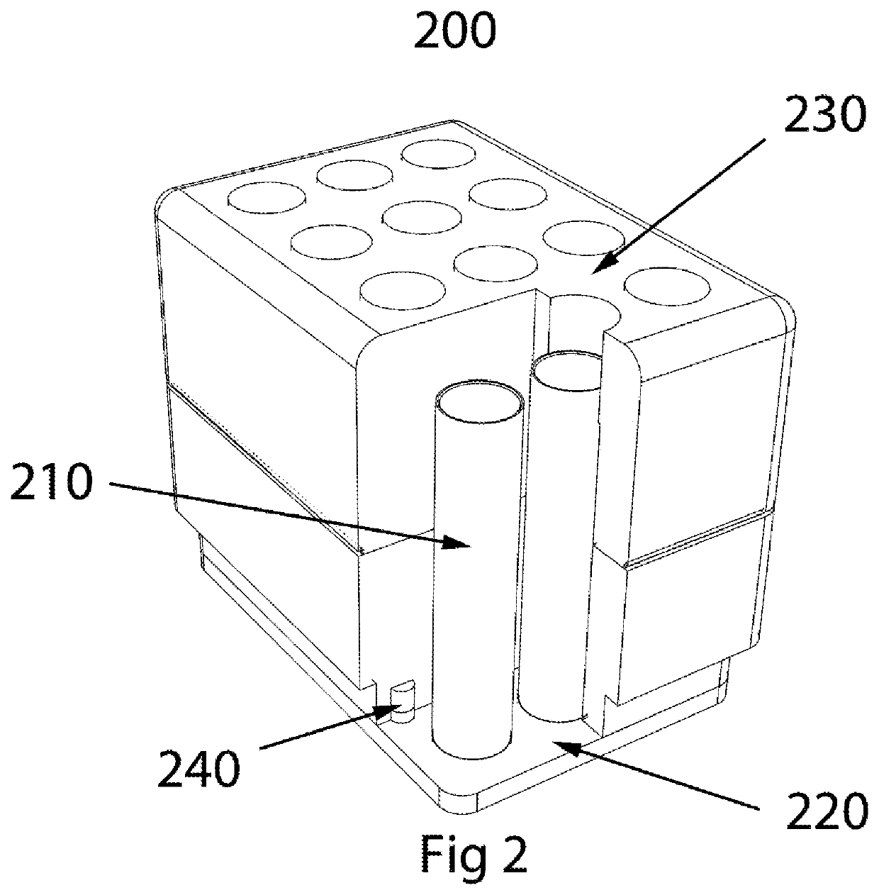
[0039]FIG. 7 shows a device of the invention and illustrates how the invention provides thermo-conductive cores for sample vessels of smaller size and greater array density. The device has a core 700 comprising the surrounding thermo-conductive material and a base that may be constructed as an integral unit that is machined directly from a block of thermo-conductive alloy.

[0040]FIG. 8 shows the thermo-conductive core in FIG. 7 as 820 encased in an insulating shell 810. The shell is removable and bonded by a slip friction fit to the core.

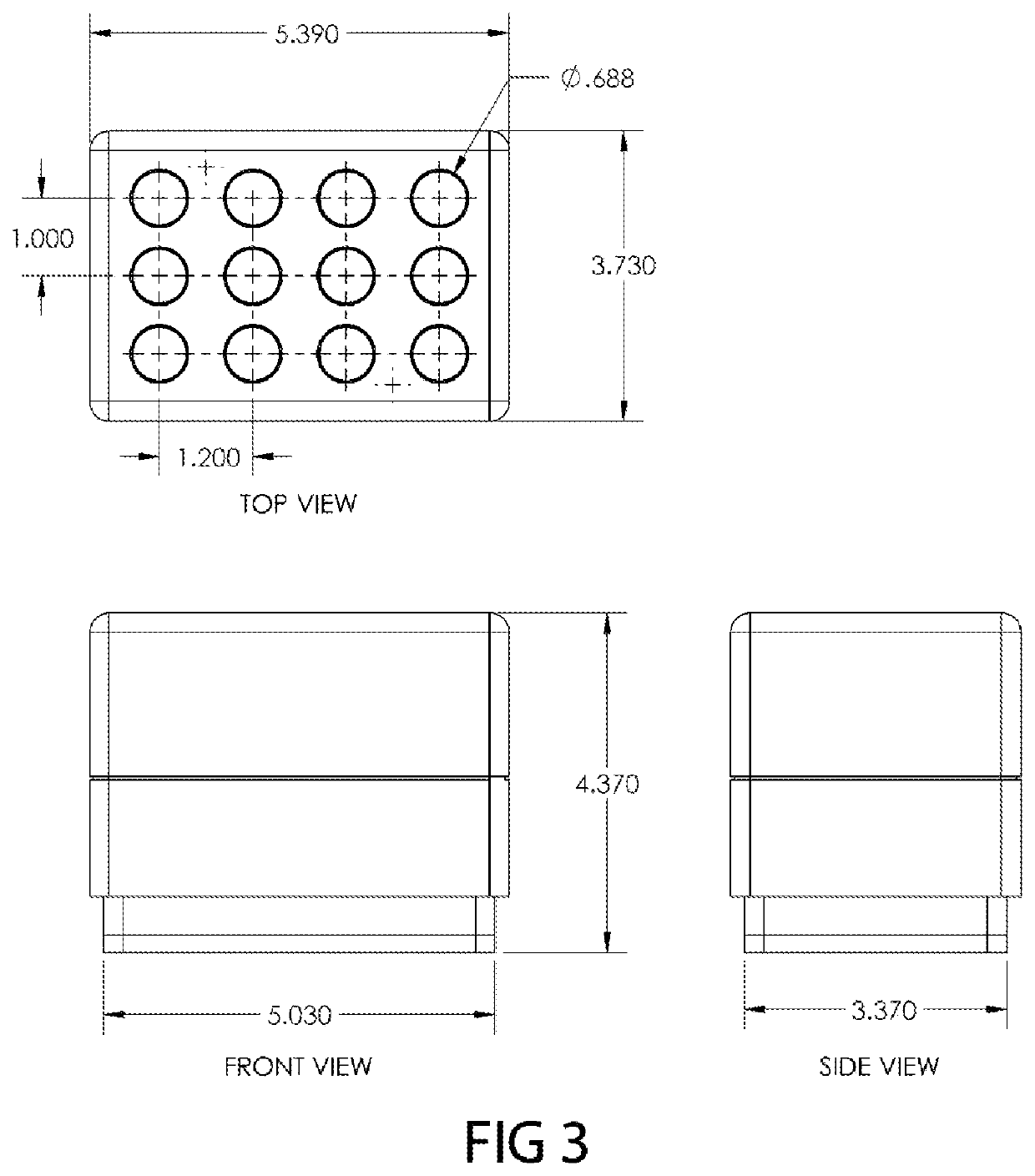
[0041]The device in FIGS. 7 and 8 has the over-all dimensions shown in FIG. 9 with outside rectangular dimensions of 5.39 inches in length and 3.73 inches in width. The base has dimensions of 5.03 inches by 3.37 inches. The height of the device including base thickness is 2.09 inches.


PUM


Abstract

A portable heat transfer device for transferring thermal energy to and / or from laboratory tubes, clinical vials, specimen vials, laboratory vials, serum vials, drug vials and laboratory containers is provided. The heat transfer device comprises an insulated, thermally conductive heat conduit system and base for the purpose of exchanging heat between the laboratory container and a thermoregulatory device.

Description

RELATED APPLICATION[0001]This application claims priority to U.S. Provisional Patent Application Ser. No. 61 / 736,907, filed Dec. 13, 2012 and titled THERMAL ENERGY TRANSFER DEVICE, which is incorporated herein by reference in its entirety.FIELD OF THE INVENTION[0002]The invention relates to heat transfer devices and methods for using the same. In particular, some aspects of the heat transfer devices are adapted to be used with various laboratory sample containment tubes in conjunction with thermoregulatory devices.BACKGROUND OF THE INVENTION[0003]Temperature control is necessary for many laboratory specimens and is often critical for biological samples for which permanent changes in the sample integrity may occur when stored under improper conditions. While refrigeration and freezing are adequate solutions for temporary or archival storage, temperature management for samples becomes more challenging under conditions where the samples are in the open, as when being manipulated on the...

Claims


Application Information

Patent Timeline
Patent Type & Authority Patents(United States)
IPC IPC(8): B01L7/00B01L9/06
CPCB01L7/00B01L9/06B01L2300/1805B01L2300/1883
Inventor SCHRYVER, BRIAN
Owner COOL LAB LLC
Why Eureka
Try Eureka