
Rotatable and adjustable hose for gas turbine

a flexible hose, rotating technology, applied in the direction of mechanical equipment, machines/engines, couplings, etc., can solve the problems of limited flexibility of each hose, inability the hose might not be able to provide a sufficient connection with the combustion chamber and/or the piping manifold, etc., to reduce the number of configurations leading to a possible mismatch, reduce the amount of tim

Active Publication Date: 2020-07-14
GE INFRASTRUCTURE TECH INT LLC
View PDF2 Cites 0 Cited by
  • Summary
  • Abstract
  • Description
  • Claims
  • Application Information

AI Technical Summary

Benefits of technology

The adaptable hose design reduces the need for new hoses or force-fitting, minimizing downtime and preventing undesired end angles, thereby enhancing the reliability and efficiency of gas turbine operations.

Problems solved by technology

However, the flexibility of each hose is limited by the properties of the material from which the hose is formed.
In addition, the thickness and diameter of the hose may further limit the flexibility of the hose.
When there is a mismatch, the hose might not be able to provide a sufficient connection with the combustion chamber and / or the piping manifold.
When a mismatch is unavoidable, a new flexible hose or an adaptor may need to be ordered, thereby increasing the amount of time needed to bring the gas turbine online.
Alternatively, the mismatched flexible hose may be forced into the desired connection, thereby resulting in undesired end angles in the flexible hose, which could lead to suboptimal performance of the combustion chamber and / or flexible hose.
The undesired end angles may also lead to premature hose wear and / or hose failure.

Method used


Image

  • Rotatable and adjustable hose for gas turbine
  • Rotatable and adjustable hose for gas turbine
  • Rotatable and adjustable hose for gas turbine

Examples


Embodiment Construction

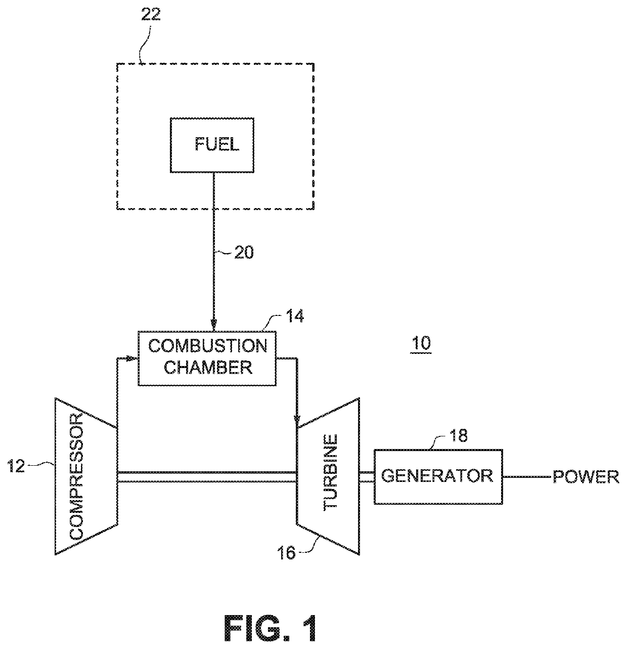
[0025]FIG. 1 illustrates an exemplary but non-limiting system that includes a gas turbine engine 10 with a compressor 12, a combustion chamber 14, a turbine 16, and a generator 18. The gas turbine engine 10 runs on a combustible fuel delivered through a fuel line 20. A fuel delivery circuit 22 may contain several lines (fuel, purge air, etc), but is illustrated with a minimal number of lines for simplicity.

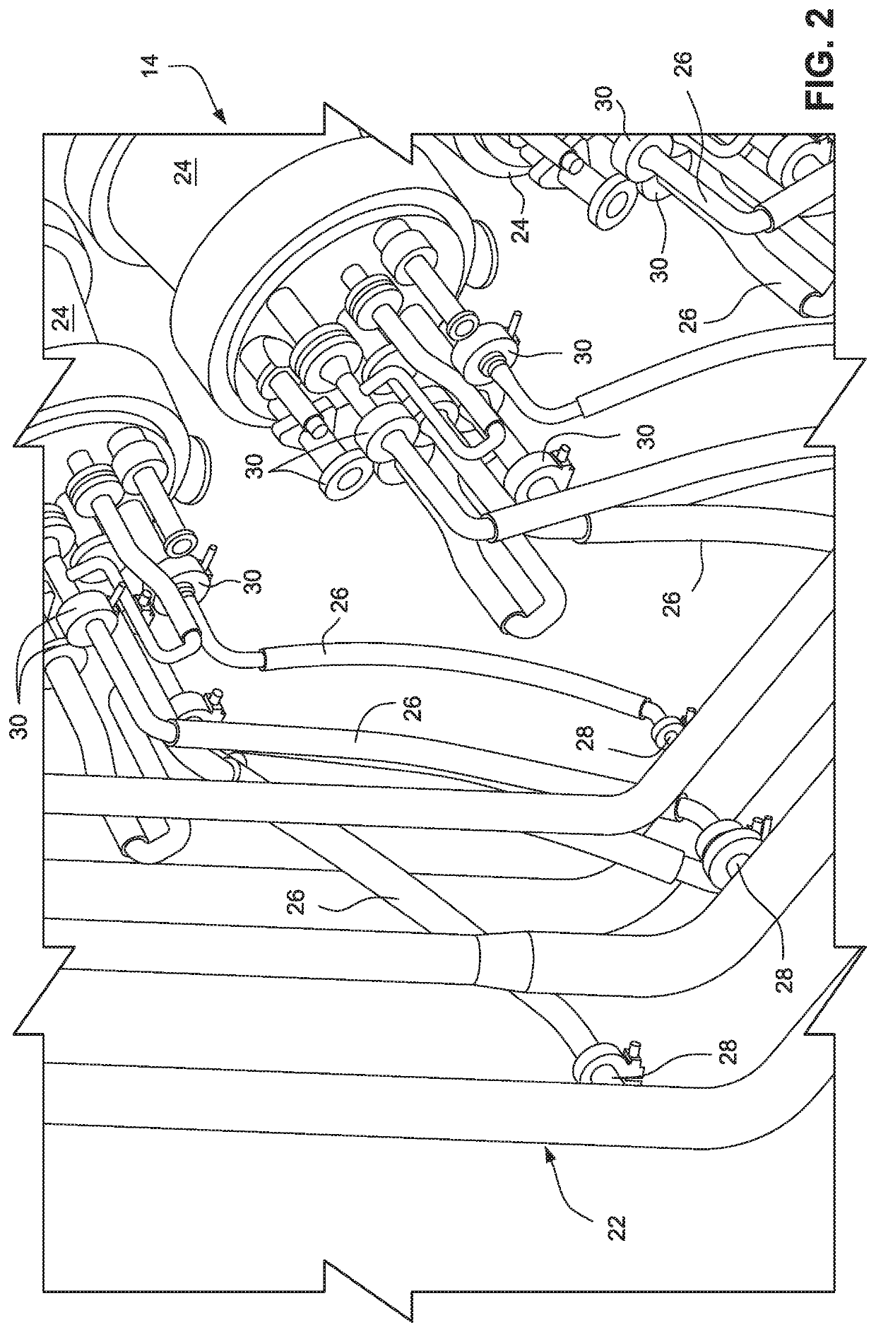
[0026]FIG. 2 is a more detailed illustration of the fuel delivery circuit 22 and the combustion chamber 14. The fuel delivery circuit 22 may include a piping manifold. In addition, the combustion chamber 14 may include a plurality of cans 24. The piping manifold may supply fuel to the cans 24 by way of a plurality of flexible hoses 26. As can be seen, the outlets 28 of the fuel delivery circuit 22 and the inlets 30 of the cans 24 may be axially offset.

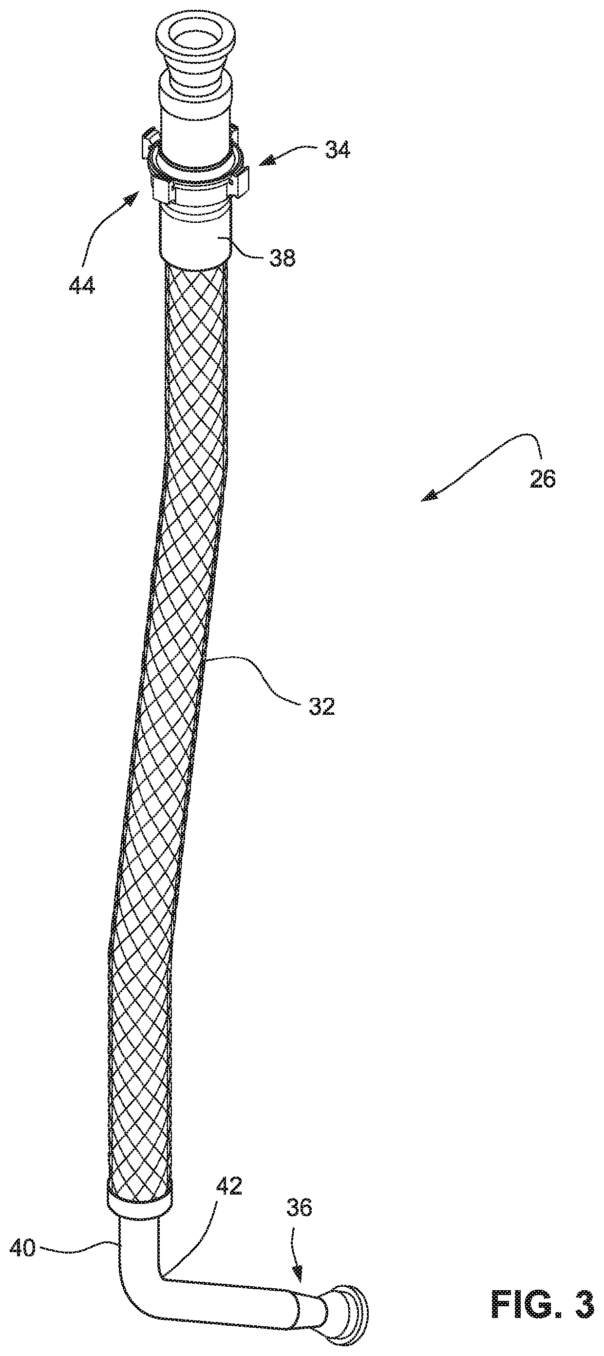
[0027]FIG. 3 illustrates one of the flexible hoses 26 illustrated in FIG. 2. The flexible hose 26 may include a central flexible po...


PUM


Abstract

A gas turbine engine system includes a fuel delivery circuit configured to convey fuel, a combustion chamber configured to combust the fuel, and a flexible hose that fluidly connects the fuel delivery circuit to the combustion chamber. The flexible hose includes a combustion chamber connector portion attached to the combustion chamber, a fuel delivery circuit connector portion attached to the fuel delivery circuit, and a central flexible portion connecting the first connector portion to the second connector portion. The central flexible portion is made of a flexible material. In addition, the fuel delivery circuit connector portion includes a pivotal assembly with an adjustable end that is pivotal relative to a central longitudinal axis of the central flexible portion of the flexible hose when the central flexible portion is in a straight condition.

Description

FIELD OF THE INVENTION[0001]The subject matter disclosed herein relates to supplying fluid to a gas turbine component and other large industrial machines. The subject matter disclosed herein relates particularly to a rotatable and adjustable flexible hose for supplying fuel to a gas turbine combustion chamber.BACKGROUND OF THE INVENTION[0002]An industrial gas turbine includes a combustor formed by a circular array of combustion chambers, which are also referred to as combustion cans. Each chamber has an end cover that includes openings which receive fuel by way of a dedicated flexible hose. The flexible hoses are, in turn, attached to a manifold that supplies the fuel to the system.[0003]By contorting the flexible hoses, the flexible hoses are able to account for some positional tolerances between the manifold outlets and the combustion chamber openings. However, the flexibility of each hose is limited by the properties of the material from which the hose is formed. In addition, the...

Claims


Application Information

Patent Timeline
Patent Type & Authority Patents(United States)
IPC IPC(8): F02C7/00F02C7/22F16L37/52F16L27/06
CPCF16L37/52F02C7/222F02C7/22F16L27/06
Inventor SOTO, JESUS WILFRIDOGARZA, LUISPATINO, JUAN
Owner GE INFRASTRUCTURE TECH INT LLC
Learn More