Unlock instant, AI-driven research and patent intelligence for your innovation.
Nano-patterning methods including: (1) patterning of nanophotonic structures at optical fiber tip for refractive index sensing and (2) plasmonic crystal incorporating graphene oxide gas sensor for detection of volatile organic compounds
Active Publication Date: 2020-07-28
IOWA STATE UNIV RES FOUND
View PDF13 Cites 17 Cited by
Summary
Abstract
Description
Claims
Application Information
AI Technical Summary
This helps you quickly interpret patents by identifying the three key elements:
Problems solved by technology
Method used
Benefits of technology
Benefits of technology
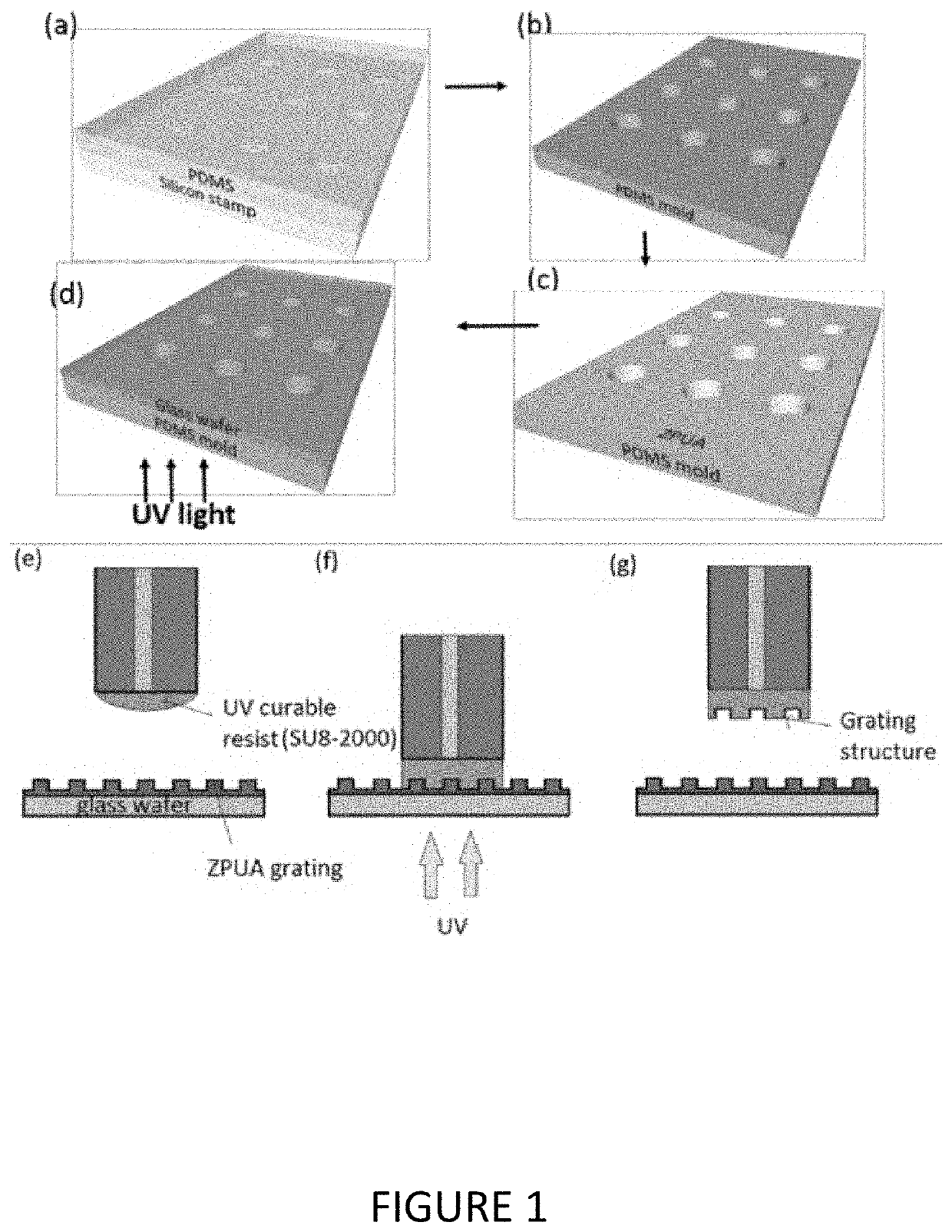
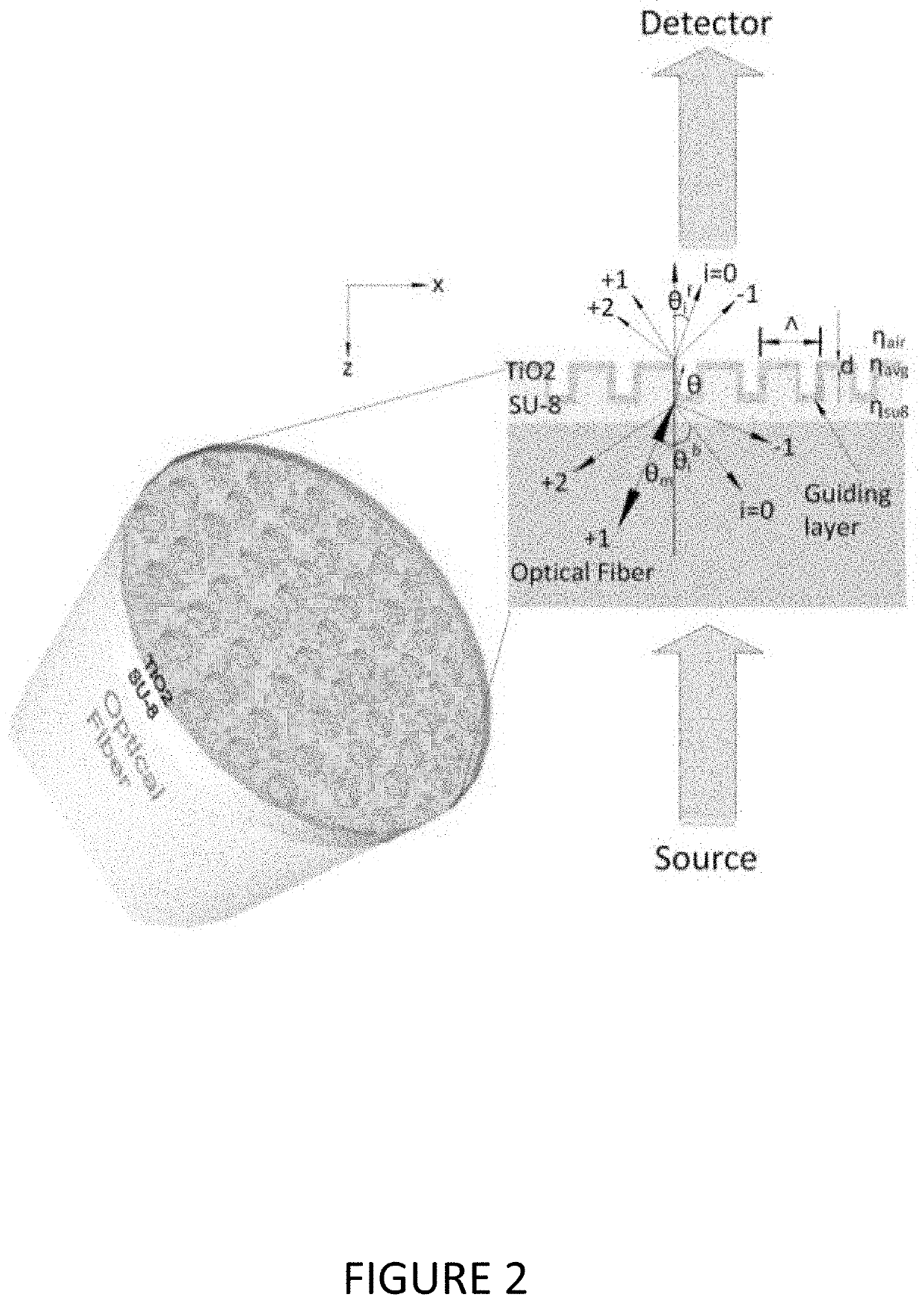
The present invention is about methods, apparatus, and systems for nanopatterning that offer high resolution and rapidity. The invention can be applied to create a variety of functional surfaces including but not limited to tunable waveguides and remote sensing. The invention also provides for the use of nanopatterning techniques in different ways for different functions such as sensing, monitoring, and optical techniques. Additionally, the invention includes a simplified and efficient process that can achieve high-resolution nanopatterning on fiber tips. Overall, the invention addresses the problems and deficiencies in the state of the art and offers an improved solution for nanopatterning.
Problems solved by technology
Yet the minute scale provides significant challenges to that goal.
However, reported attempts can be complex and resource intensive.
Method used
Image
Click on the blue label to locate the original text in one second.
Reading with bidirectional positioning of images and text.
Examples
example 1
C. Specific Example 1
[0089]The following specific example relates to FIGS. 1-13 and is also discussed in Shawana Tabassum, Yifei Wang, Jikang Qu, Qiugu Wang, Seval Oren, Robert J. Weber, Meng Lu, Ratnesh Kumar, and Liang Dong, Patterning of nanophotonic structures at optical fiber tip for refractive index sensing, 2016 IEEE SENSORS, Orlando, Fla., 2016, pp. 1-3, which is incorporated by reference herein.
[0090]The paper extends the conference version [45](see http: / / ieeexplore.ieee.org / abstract / document / 7808581 / ), incorporated by reference herein.
[0091]See also Article in IEEE Sensors Journal—September 2017 DOI: 10.1109 / JSEN.2017.2748593, available on-line Oct. 23, 2017 at:
[0092]https: / / www.researchgate.net / profile / Shawana_Tabassum / publication / 319349510_Nanopatterned_Optical_Fiber_Tip_for_Guided_Mode_Resonance_and_Application_to_Gas_Sensing / links / 59ae3da90f7e9bdd115 eb9cd / Nanopatterned-Optical-Fiber-Tip-for-Guided-Mode-Resonance-and-Application-to-Gas-Sensing.pdf and which is incorpo...
example 2
D. Specific Example 2
[0196]The following more specific example relates to FIG. 14-24 and is discussed at Shawana Tabassum; Qiugu Wang; Wentai Wang; Seval Oren; Md. Azahar Ali; Ratnesh Kumar; Liang Dong. “Plasmonic crystal gas sensor incorporating grapheneoxide for detection of volatile organic compounds,” 2016 IEEE 29th International Conference on Micro Electro Mechanical Systems (MEMS), Shanghai, 2016, pp. 913-916, which is incorporated by reference herein.
[0197]See also, Tabassum, et al., Plasmonic Crystal based Gas Sensor towards an Optical Nose Design, IEEE Sensors Journal, Vol. 17, No. 19, Oct. 1, 2017, pp. 6210-6223, incorporated by reference in its entirety herein.
Plasmonic Crystal Based Gas Sensor Towards an Optical Nose Design
[0198]Abstract—This paper presents a high-sensitivity gas sensor based on plasmonic crystal incorporating a thin layer of graphene oxide (GO). The plasmonic crystal consists of a periodic array of polymeric nanoposts with gold (Au) disks at the top an...
PUM
Property
Measurement
Unit
Thickness
aaaaa
aaaaa
Thickness
aaaaa
aaaaa
Thickness
aaaaa
aaaaa
Abstract
A technique, and its applications, for high resolution, rapid, and simple nanopatterning. The general method has been demonstrated in several forms and applications. One is patterning nanophotonic structures at an optical fiber tip for refractive index sensing. Another is patterning nanoresonator structures on a sensor substrate for plasmonic effect related detection of VOCs. In the latter example, a grapheneoxide coated plasmonic crystal as a gas sensor capable of identifying different gas species using an array of such structures. By coating the surface of multiple identical plasmonic crystals with different thicknesses of Graphene-Oxide (GO) layer, the effective refractive index of the GO layer on each plasmonic crystal is differently modulated when exposed to a specific gas. Identification of various gas species is accomplished using pattern recognitionalgorithm.
Description
CROSS-REFERENCE TO RELATED APPLICATIONS[0001]This application claims the benefit of Provisional Application U.S. Ser. No. 62 / 411,402 filed on Oct. 21, 2016, all of which is herein incorporated by reference in its entirety.GOVERNMENT RIGHTS CLAUSE[0002]This invention was made with Government support under Grant Number CCF1331390 awarded by the National Science Foundation. The government has certain rights in the invention.BACKGROUND OF THE INVENTIONA. Field of the Invention[0003]The present invention relates to nano-patterning and grapheneoxide (GO) layering on functional surfaces and devices including improved fabrication methods and applications.[0004]In one non-limiting example, the patterning is at the tip of an optic fiber for waveguide and remote sensing functionalities in gaseous, e.g., volatile organic compounds (VOCs) or aqueous medium. The absorbed VOCs on the GO layer, alter the guided mode resonance leading to detection.[0005]In another non-limiting example, the patterni...
Claims
Application Information
Patent Timeline
Application Date:The date an application was filed.
Publication Date:The date a patent or application was officially published.
First Publication Date:The earliest publication date of a patent with the same application number.
Issue Date:Publication date of the patent grant document.
PCT Entry Date:The Entry date of PCT National Phase.
Estimated Expiry Date:The statutory expiry date of a patent right according to the Patent Law, and it is the longest term of protection that the patent right can achieve without the termination of the patent right due to other reasons(Term extension factor has been taken into account ).
Invalid Date:Actual expiry date is based on effective date or publication date of legal transaction data of invalid patent.
