Rotating magnetic disc medical analyzer and coagulation profiler

Active Publication Date: 2020-08-11
IFIRST MEDICAL TECH INC
View PDF106 Cites 2 Cited by
  • Summary
  • Abstract
  • Description
  • Claims
  • Application Information

AI Technical Summary

Benefits of technology

[0008]The invention solves the existing problems by providing new base medical

Problems solved by technology

In these types of traumatic injury, the incidences of coagulation abnormalities are high.
For example, natural supplies of proteins such as Factor VII are quickly depleted after trauma, which can quickly lead to hemorrhage-related death.
In addition it has been shown that PT and PTT tests do not predict coagulation abnormalities as effectively as coagulation profiles, such as thrombelastography (TEG) shown in F

Method used


Image

  • Rotating magnetic disc medical analyzer and coagulation profiler
  • Rotating magnetic disc medical analyzer and coagulation profiler
  • Rotating magnetic disc medical analyzer and coagulation profiler

Examples


second embodiment

[0071]the BioMEMS device is shown in FIG. 3. In this embodiment a fixed magnet 51 is coupled to the disc. In this fixed magnet case, the rotation would be induced by rotating the cartridge 12 or well 14 within the cartridge. In this fixed magnet embodiment, the motion induced to the disc would be traced directly, with no differencing necessary. In this case the tracked motion could be directly used as the profile trace. Prior to the onset of coagulation there would be no motion coupled and the disc would oscillate uninhibited within the well. With no motion induced, the coagulation profile would be zero. In the fixed magnet case as the coagulation increases, the coupling would increase inducing more motion as coagulation continues. At MA the maximum amount of motion would be induced through the magnet.

third embodiment

[0072]a coagulation profiling BioMEMS device is shown FIG. 4. This device has a center disc 61 and an outer ring 62 that is suspended by torsion springs 63. As the blood begins to coagulate, the rotating inner disc 61, actuated via an oscillating magnet, couples to the outer ring 62. This couples a reciprocating motion to the outer ring 2. At MA the maximum amount of motion would be induced through the magnet.

[0073]The BioMEMS embodiments shown are not all of the possible variations. For instance, one embodiment could use disc fixed to the center of the well and actuate a ferrous ring in the well. These variation of the described embodiments are apparent to one skilled in the art.

[0074]The measurement provided by the invention is impervious to motion. Due to the extremely small dimensions of the BioMEMS device, compared to the conventional size of TEG and ROTEM, the measurement is highly impervious to motion. The small mass of the device and small volume residing in the well present...


PUM


Abstract

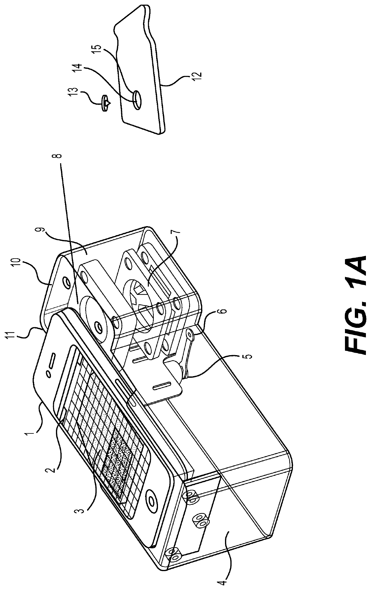
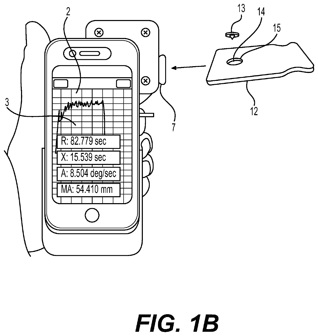
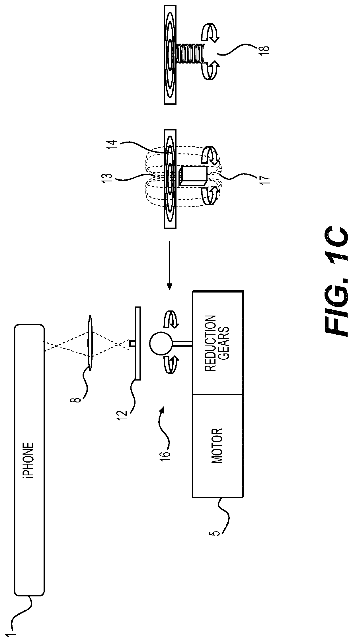
A medical analyzer and coagulation profiler performs various interrogations on specimens. A motor with reduction gearing moves and a video camera observes the samples, the cartridges or parts thereof. Changes in images are compared and recorded with a central processor that controls a display. Power supply, temperature controller, motor and gearing are mounted in a box which attaches to a smartphone. The smartphone provides the video camera, illumination and central processor that control the movement, temperature and display. The device makes testing simpler for small hospitals, clinics, ambulances, remote locations and individuals and controls a number of parallel or serial devices operating simultaneously or sequentially. A cartridge insertion actuates a circular motion to generate a blood profile based on changes. Change is analyzed with a video camera and processor such as in a smartphone and is plotted to show an amplitude and time. A smartphone provides a specific movement pattern.

Description

[0001]This application claims the benefit as a continuation of U.S. patent application Ser. No. 15 / 380,856 filed on Dec. 15, 2016, which is in turn a continuation of U.S. patent application Ser. No. 14 / 526,057 filed on Oct. 28, 2014, which is a nonprovisional of U.S. Provisional Application No. 61 / 896,405 filed Oct. 28, 2013, each of the foregoing of which are hereby incorporated by reference in their entireties as if fully set forth herein. This application claims the benefit of U.S. Provisional Application No. 61 / 896,405 filed Oct. 28, 2013, which is hereby incorporated by reference in its entirety as if fully set forth herein.[0002]This invention was made with government support under Contract No. W81XWH-11-C-0055 awarded by the U.S. Army Medical Research Acquisition Activity. The government has certain rights in the invention.BACKGROUND OF THE INVENTION[0003]Five million people around the world die of trauma on an annual basis. Up to 20% of these deaths are preventable with bett...

Claims


Application Information

Patent Timeline
IPC IPC(8): G01N33/86G01N11/14
CPCG01N11/14G01N2011/147G01N33/4905B01L3/502B01L2300/041B01L2300/0803B01L2300/0848B01L2400/043G01N33/86G01N2800/224G01N2800/7033
Inventor JOSEPH, LUKE B.HASLING, THOMAS A.
Owner IFIRST MEDICAL TECH INC
Why Eureka
Try Eureka