Alternating pressure melt impregnation device and melt impregnation method using the same

a technology of impregnation device and melt, which is applied in the direction of liquid surface applicators, coatings, etc., can solve the problems of easy breakage of yarn, increase of impregnation rate, and complicated equipment structure, so as to increase or maintain the pressure of the melt injection area, reduce the pressure, and strengthen the effect of uniform distribution

Active Publication Date: 2020-08-18
KINGFA SCI & TECH CO LTD
View PDF8 Cites 8 Cited by
  • Summary
  • Abstract
  • Description
  • Claims
  • Application Information

AI Technical Summary

Benefits of technology

[0008]The present invention is to provide an alternating pressure melt impregnation device with a simple structure, a good impregnating effect and few broken yarns, and to provide a melt impregnation method with a high impregnation rate and a high production stability.
[0015]In the alternating pressure melt impregnation device and the melt impregnation method according to the present invention, the resin melt is squirted from each resin melt runner on the upper die and the lower die of the melt injection area, and thus the squirted resin melt is enable to be squirted directly on an upper surface and a lower surface of the continuous fiber bundle which is entering into the impregnation chamber. Impregnation and infiltration for both surfaces of the continuous fiber bundle are primarily completed by a squirted pressure. As the resin melt inside the impregnation chamber flows to the decompression chambers at both sides of the impregnation chamber, perturbation in different directions such as forward, backward, radial and slant is generated, resulting in a varied direction of the resin melt. When the resin melt flows to the throttle plate, a resistance of the throttle plate leads to an increasing pressure of the resin melt inside the impregnation chamber, which prompts the resin melt to break through a surface tension of the continuous fiber bundle and realizes a re-impregnation for the continuous fiber bundle. Then when the resin melt is squirted to the decompression chamber from the filament-moving hole on the throttle plate, the pressure is decreased. After the resin melt enters into the decompression chamber by a relatively small filament-moving hole, a section of the resin melt is enlarged and a radial flow is generated due to the Barus effect, which further strengthens a uniform distribution inside the continuous fiber bundle of the resin melt inside the decompression chamber, and achieves an object of complete cladding and infiltration. Besides, the decompression chamber can provide a space as required when the resin melt expands. Increasing a number of the decompression chamber is advantageous to increase or maintain a pressure of the melt injection area. A drawing process of the continuous fiber bundle always remains a straight and flat state instead of a curved impregnation path, and thus a velocity gradient of the resin melt would not form an overlarge shearing field. When the impregnation is performed in a condition of a high drawing speed, or even in a condition of a high resin melt viscosity, no broken yarn would take place. Through an effect of an alternating pressure, the continuous fiber bundle achieves a balanced impregnating effect, and usage of a rotating roller or a gear to increase an impregnating pressure is avoided, and thus the broken yarn caused by a friction of the continuous fiber bundle is further avoided. Additionally, since the rotating roller or the gear does not exist in the melt injection area, a structure is simpler and the maintenance is more convenient, without accumulation of winding or broken yarns. Besides, due to few broken yarns and good impregnating effect in the high drawing speed, an impregnation rate can be enormously increased and a production stability is high.

Problems solved by technology

It can be known that increasing a melt pressure, reducing a thickness of the fiber bundle and decreasing a melt viscosity can increase an impregnation rate.
When the impregnation is performed in a condition of high drawing speed, a broken yarn is caused easily.
Besides, since a relatively large number of rotating rollers or gears present inside the impregnation area, a complicated structure of equipment and difficult cleaning and maintenance are caused.

Method used


Image

  • Alternating pressure melt impregnation device and melt impregnation method using the same

Examples


embodiment 1

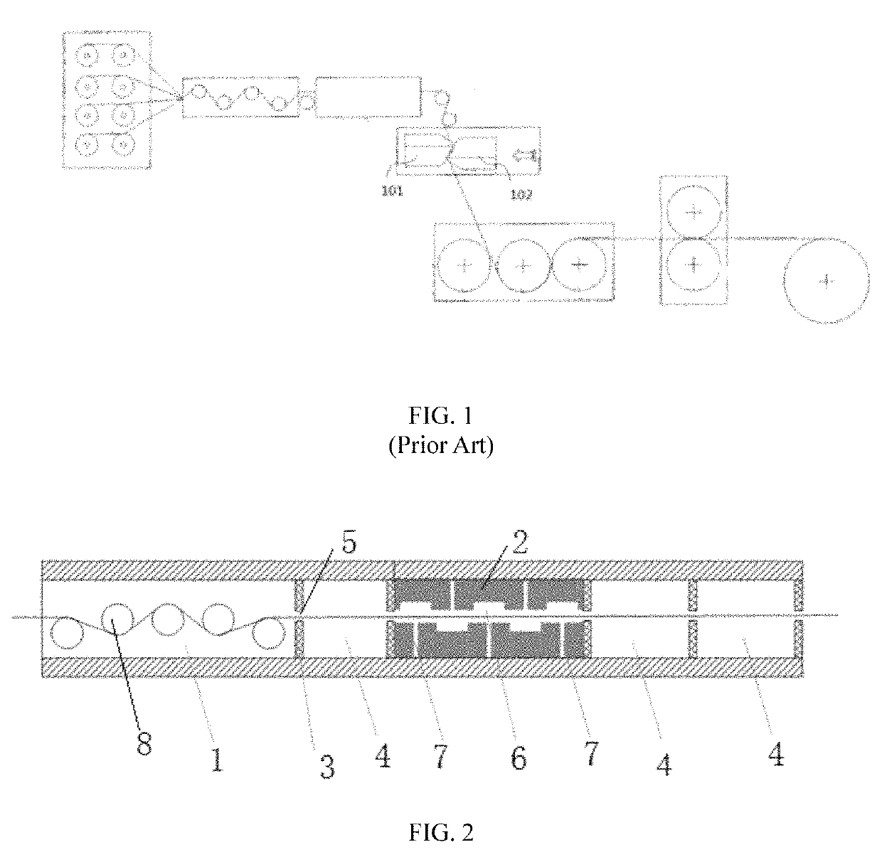
[0036]The above-described alternating pressure melt impregnation device was used to impregnate the continuous fiber bundle by the above-described melt impregnation method. Particularly, the fiber pre-dispersion area 1 comprised two tension roller sets arranged front and rear. A diameter of the tension roller 8 in each tension roller set was 50 mm, a distance between shafts of two tension rollers 8 in each tension roller set was 200 mm, and a temperature for preheating was 200° C. The upper die was provided with two resin melt runners 7, and the lower die was provided with three resin melt runners 7. Each resin melt runner 7 of the upper die and each resin melt runner 7 of the lower die were in a staggered arrangement. A vertical interval between an outlet plane of the resin melt runner 7 on the upper die and an outlet plane of the resin melt runner 7 on the lower die was 50 mm, and a diameter at an outlet of the resin melt runner 7 was 10 mm. An outlet end of the resin melt runner 7...

embodiment 2

[0041]The vertical interval between the outlet plane of the resin melt runner 7 on the upper die and the outlet plane of the resin melt runner 7 on the lower die was changed to 2 mm. Other details were the same as Embodiment 1. The drawing speed under the circumstance without the broken yarn was tested as 65 m / min via the tachometer.

embodiment 3

[0042]The vertical interval between the outlet plane of the resin melt runner 7 on the upper die and the outlet plane of the resin melt runner 7 on the lower die was changed to 20 mm, and the diameter at the outlet of each resin melt runner 7 was 5 mm. Other details were the same as Embodiment 1. The drawing speed under the circumstance without the broken yarn was tested as 67 m / min via the tachometer.


PUM

PropertyMeasurementUnit
diameteraaaaaaaaaa
diameteraaaaaaaaaa
diameteraaaaaaaaaa

Abstract

An alternating pressure melt impregnation device and a melt impregnation method, including having a resin melt squirted from each resin melt runner on an upper die and a lower die of a melt injection area, and thus the squirted resin melt is enable to be squirted directly on an upper surface and a lower surface of a continuous fiber bundle which is entering into an impregnation chamber. Impregnation and infiltration for both surfaces of the continuous fiber bundle are primarily completed by a squirted pressure. The resin melt inside the impregnation chamber flows to a decompression chambers at both sides of the impregnation chamber. When the resin melt flows to a throttle plate, a re-impregnation for the continuous fiber bundle is realized. Then the pressure is decreased and a section of the resin melt is enlarged and a radial flow is generated due to the Barus effect.

Description

CROSS-REFERENCE TO RELATED APPLICATION[0001]This application claims the priority benefit of China application serial no. 201711367963.5, filed on Dec. 18, 2017. The entirety of the above-mentioned patent application is hereby incorporated by reference herein and made a part of this specification.TECHNICAL FIELD[0002]The present invention relates to an alternating pressure melt impregnation device and a melt impregnation method, and specifically relates to a melt impregnation device and a melt impregnation method for a continuous fiber-reinforced thermoplastic resin composite material.BACKGROUND[0003]Continuous fiber-reinforced thermoplastic resin composite material is a composite material using an impregnation device to impregnate and reinforce a continuous fiber with a molten resin. Compared with a short fiber-reinforced thermoplastic resin composite material, the continuous fiber-reinforced thermoplastic resin composite material has advantages such as a high strength, a good impac...

Claims


Application Information

Patent Timeline
Patent Type & Authority Patents(United States)
IPC IPC(8): B29C70/52B05C3/132B05C3/12B29B15/12B05C3/152B29K101/12
CPCB05C3/152B29C70/523B05C3/125B29C70/528B05C3/132B29B15/122B29C70/527B29K2101/12B29C70/46B29B15/125B29C70/526B29C70/54
Inventor HUANG, XIANBOXIN, WEILI, YONGHUACHEN, CHUNHUACHEN, DAHUA
Owner KINGFA SCI & TECH CO LTD
Why Eureka
Try Eureka