
Radiofrequency power combiner or divider having a transmission line resonator

a technology transmission line, which is applied in the direction of amplifiers, amplifiers with semiconductor devices/discharge tubes, amplifiers, etc., can solve the problems of large size of rf power combiner, inability to receive rf power from a single power source, and complex process of rf power combining

Active Publication Date: 2020-08-18
GENERAL ELECTRIC CO
View PDF11 Cites 0 Cited by
  • Summary
  • Abstract
  • Description
  • Claims
  • Application Information

AI Technical Summary

Problems solved by technology

For applications that use a large amount of RF power, it may not be possible to receive the RF power from a single power source.
RF power combining can be a complex process that addresses various challenges, including impedance transformation and matching, losses, bandwidth, and power limitations.
Size of the RF power combiner is another challenge, especially for applications in which the frequency range is less than 300 megahertz (MHz).
However, it can be difficult to combine several RF power combiner units in one stage, thereby necessitating several power-combining stages.
Each stage adds complexity, size, and additional RF losses to the overall system.
Power vacuum tubes, such as triodes and tetrodes, can be expensive.
Circulators can be expensive and also add complexity and size to the overall system.
Other active feedback protection systems can be used, but they can also add complexity and size to the overall system.
As such, power dividers may have similar challenges, such as those described above.

Method used


Image

  • Radiofrequency power combiner or divider having a transmission line resonator
  • Radiofrequency power combiner or divider having a transmission line resonator
  • Radiofrequency power combiner or divider having a transmission line resonator

Examples


Embodiment Construction

[0051]The following detailed description of certain embodiments will be better understood when read in conjunction with the appended drawings. To the extent that the figures illustrate diagrams of the functional blocks of various embodiments, the functional blocks are not necessarily indicative of the division between hardware circuitry.

[0052]As used herein, an element or step recited in the singular and proceeded with the word “a” or “an” should be understood as not excluding plural of said elements or steps, unless such exclusion is explicitly stated, such as by stating “only a single” element or step. Furthermore, references to “one embodiment” are not intended to be interpreted as excluding the existence of additional embodiments that also incorporate the recited features. Moreover, unless explicitly stated to the contrary, embodiments “comprising” or “having” an element or a plurality of elements having a particular property may include additional such elements not having that ...


PUM


Abstract

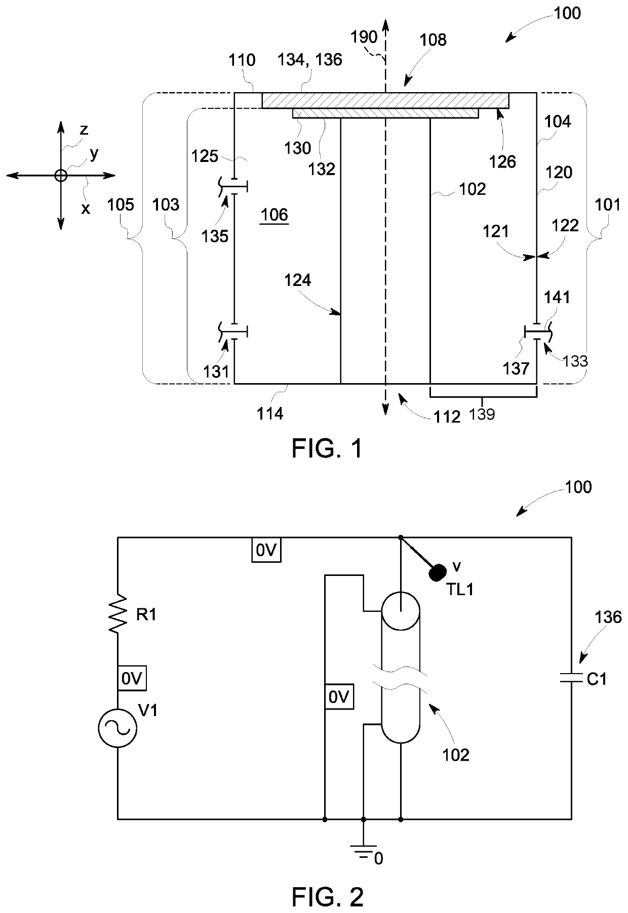
Power combiner / divider includes a transmission line (TL) resonator having an inner conductor, an outer conductor that surrounds the inner conductor, and a cavity between the inner conductor and the outer conductor. The inner conductor and the outer conductor are electrically connected at a proximal end of the TL resonator. The power combiner / divider also includes coupling elements extending through respective openings of the outer conductor and into the cavity. The power combiner / divider also includes a capacitive element connected to at least one of the inner conductor or the outer conductor. The capacitive element capacitively couples the inner conductor and the outer conductor at a distal end of the TL resonator.

Description

BACKGROUND[0001]The subject matter herein relates generally to power combiners that combine radio frequency (RF) power from multiple sources to a common load or to power dividers that split the RF power from a common source to multiple loads.[0002]High-power RF systems that operate at a designated frequency or within a frequency range are used within various technological fields, such as communication, industrial processing, medical imaging, and physics-related research. For example, particle accelerators may be used to generate isotopes. Particle accelerators, such as cyclotrons, include high-power RF generators that create electrical fields for accelerating particles. Static magnetic fields are provided by electromagnets and a magnet yoke that surrounds the acceleration chamber. The electrical fields are generated by a pair of RF dees that are located within the acceleration chamber. To operate the RF dees within the acceleration chamber, a considerable amount of RF power (e.g., 5...

Claims


Application Information

Patent Timeline
Patent Type & Authority Patents(United States)
IPC IPC(8): H01P5/18H01P1/12H03F3/60
CPCH01P5/183H01P1/122H03F3/602H01P3/06H01P5/16H01P7/04
Inventor BÄCKLUND, ANDREASDANCILA, DRAGOS
Owner GENERAL ELECTRIC CO
Learn More