Transformer and power supply apparatus including the same

a transformer and power supply technology, applied in the field of transformers, to achieve the effect of reducing the size and manufacturing cost of the transformer and simplifying the manufacturing process

Active Publication Date: 2020-08-25
SOLUM CO LTD
View PDF14 Cites 0 Cited by
  • Summary
  • Abstract
  • Description
  • Claims
  • Application Information

AI Technical Summary

Benefits of technology

[0010]One or more exemplary embodiments relate to a transformer capable of exhibiting good insulation performance between a magnetic core and a coil through an insertion coupling structure of a coil unit and a base, achieving miniaturization while sufficiently securing a creepage distance between the magnetic core and an output terminal, and manufacturing the transformer through simple assembly.
[0023]According to a transformer and a power supply apparatus including the same according to an exemplary embodiment, a creepage distance between a magnetic core and an output terminal may be sufficiently secured.
[0024]A manufacturing process may be simplified through an insertion coupling structure of a base and a coil unit and a size and manufacturing cost of the transformer may be reduced.

Problems solved by technology

Also, an exemplary embodiment is not required to overcome the disadvantages described above, and an exemplary embodiment may not overcome any of the problems described above.

Method used


Image

  • Transformer and power supply apparatus including the same
  • Transformer and power supply apparatus including the same
  • Transformer and power supply apparatus including the same

Examples


Embodiment Construction

[0032]Hereinafter, various embodiments will now be described more fully with reference to the accompanying drawings in which some embodiments are shown. The techniques described herein are exemplary, and should not be construed as implying any particular limitation on the present disclosure. However, in the following description, it is understood that the technology described therein may not be limited to a specific embodiment, and various modifications, equivalents, and / or alternatives of the embodiments may be included therein without departing from the principles and spirit of the present disclosure.

[0033]In the following description, unless otherwise described, the same reference numerals are used for the same elements when they are depicted in different drawings.

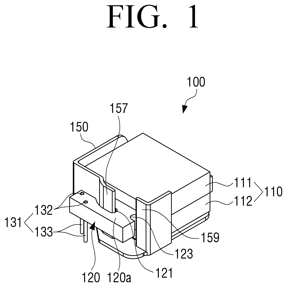
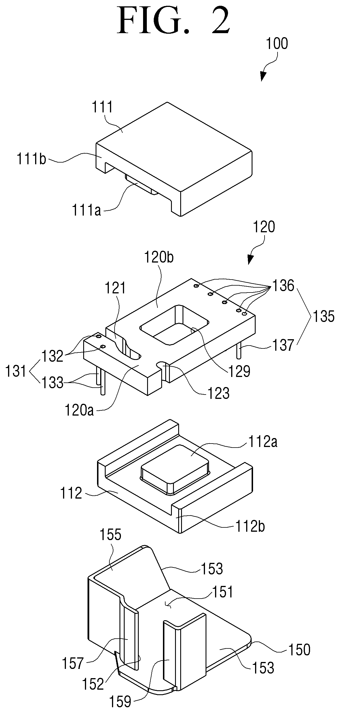
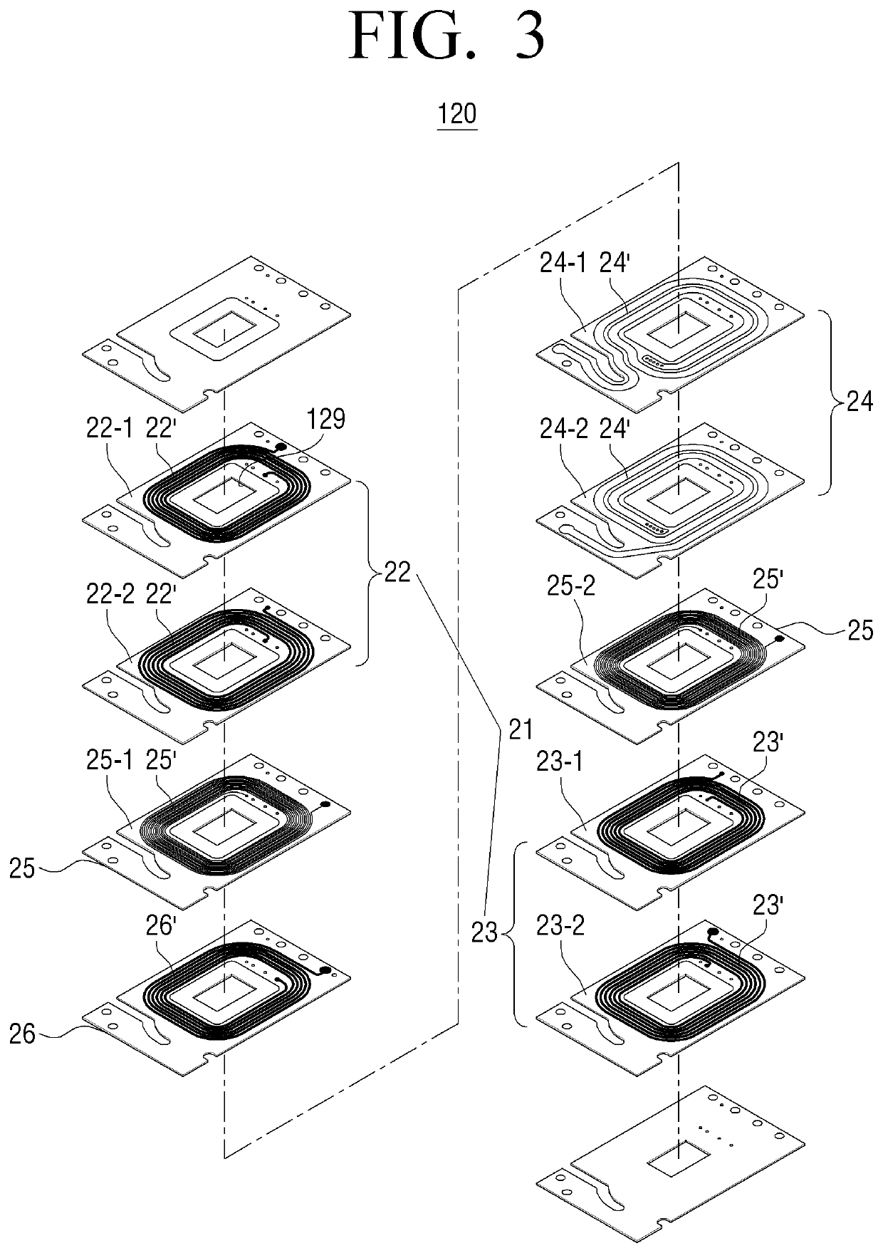
[0034]FIGS. 1 and 2 are a perspective view and an exploded perspective view illustrating a transformer according to an exemplary embodiment. FIG. 3 is an exploded perspective view illustrating layers laminated in a coil...


PUM

PropertyMeasurementUnit
conductiveaaaaaaaaaa
magneticaaaaaaaaaa
widthaaaaaaaaaa

Abstract

A transformer includes a magnetic core having an inner space, a coil unit disposed within the magnetic core and including a primary coil and a secondary coil in which layers formed with conductive patterns are laminated, and a base configured to receive the magnetic core and the coil unit. A portion of the base is inserted into and disposed in the coil unit to be interposed between an output terminal coupled to the secondary coil and the magnetic core.

Description

CROSS-REFERENCE TO RELATED APPLICATIONS[0001]This application claims priority from Korean Patent Application No. 10-2017-0092602, filed on Jul. 21, 2017, in the Korean Intellectual Property Office, the disclosure of which is incorporated herein by reference in its entirety.BACKGROUND OF THE INVENTIONField of the Invention[0002]Apparatuses and methods consistent with exemplary embodiments relate to a transformer, and more particularly, to a transformer and a power supply apparatus including the same.Description of the Related Art[0003]A power unit may be provided in a power supply apparatus and a transformer in the power unit may have a size corresponding to approximately one third of a total size of the power unit.[0004]The transformer may be an electronic component widely used to adjust an alternating current (AC) voltage in the power supply apparatus and may have a structure that a primary coil and a secondary coil are wound around a bobbin and a core is integrally coupled to the ...

Claims


Application Information

Patent Timeline
Patent Type & Authority Patents(United States)
IPC IPC(8): H01F27/24H01F27/28H01F27/29H01F27/32H01F27/02
CPCH01F27/2804H01F27/24H01F27/324H01F27/292H01F27/325H01F2027/2819H01F2027/297H01F27/027H01F2027/2809H01F27/02H01F27/06H01F27/29H01F2027/065H01F27/306
Inventor CHEON, MYEONG-SIKKIM, JUN-YOUNGBANG, YUN-SIC
Owner SOLUM CO LTD
Why Eureka
Try Eureka