
Adhesive tape

a technology of adhesive tape and adhesive layer, which is applied in the field of adhesive tape, can solve the problems of deterioration of adhesive layer adhesive force and decrease of decorative printing printability, and achieve the effect of preventing deterioration of adhesive force over time and good printability

Active Publication Date: 2020-09-01
MAXELL HLDG LTD
View PDF23 Cites 0 Cited by
  • Summary
  • Abstract
  • Description
  • Claims
  • Application Information

AI Technical Summary

Benefits of technology

This patent text describes an adhesive tape that has good printability and doesn't lose its adhesive force over time. The tape is created by forming a base using a resin layer and an adhesive layer, which are applied using coating materials. This new method improves the optical properties of the adhesive tape and reduces its thickness and weight. The technical effect of this invention is the creation of an adhesive tape that can maintain its printability and adhesive force even after extended periods of use.

Problems solved by technology

However, in an adhesive tape in which the resin layer and the adhesive layer are formed by the application, printability in decorative printing may be decreased or adhesive force of the adhesive layer may be deteriorated over time in some cases, depending on types of the resins and cross-linking agent forming the resin layer and the adhesive layer.

Method used


Image

  • Adhesive tape
  • Adhesive tape
  • Adhesive tape

Examples


example 1

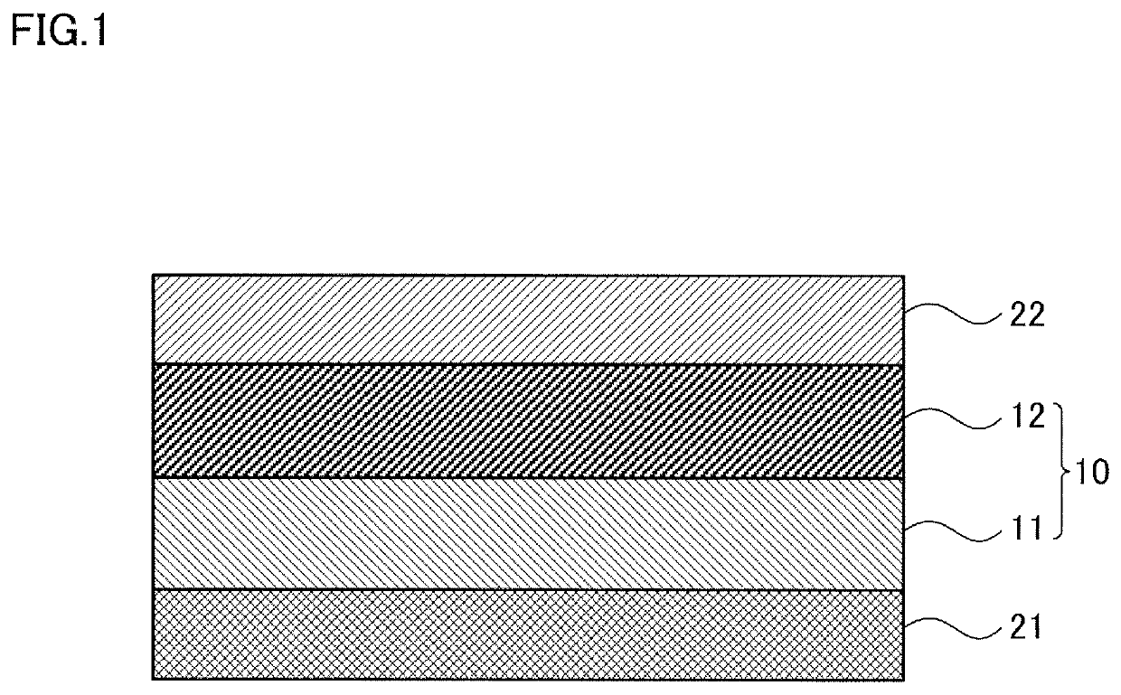
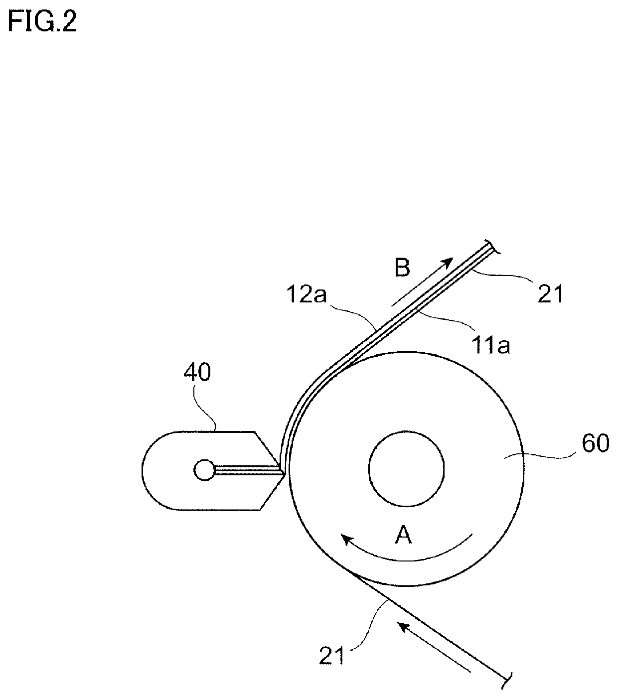
[0169]By using the coating apparatus shown in FIG. 2, the adhesive coating a and the resin coating A were simultaneously applied onto the release-treatment surface of the release liner (the first release liner 21, material: PET, thickness: 50 μm) fed from the unwinding shaft so that the adhesive coating a was placed on the upper side (the opposite side of the release liner with respect to the resin coating A), and the solvent was dried. Next, the other release liner (the second release liner 22, material: PET, thickness: 100 μm) fed from another unwinding shaft was overlaid on the dried adhesive coating a and laminated thereon, then aging was performed under an atmosphere at 40° C. for 72 hours, and the adhesive tape 10 shown in FIG. 1, in which the resin layer 11 and the adhesive layer 12 had been laminated, was obtained.

[0170]Note that, the thickness of the adhesive layer 12, after the drying and aging, was 7.5 μm, the thickness of the resin layer 11 was 7.5 μm, and the total thic...

example 2

[0171]The adhesive tape 10 in which the resin layer 11 and the adhesive layer 12 had been laminated was obtained in a similar manner to the example 1 except for using the resin coating B instead of the resin coating A.

[0172]Note that the thickness of the adhesive layer 12, after the drying and aging, was 8 μm, the thickness of the resin layer 11 was 10 μm, and the total thickness of the adhesive tape 10 which was obtained by adding the adhesive layer 12 and the resin layer 11 was 18 μm.

example 3

[0173]The adhesive tape 10 in which the resin layer 11 and the adhesive layer 12 had been laminated was obtained in a similar manner to the example 1 except for using the resin coating C instead of the resin coating A.

[0174]Note that the thickness of the adhesive layer 12, after the drying and aging, was 10 μm, the thickness of the resin layer 11 was 8 μm, and the total thickness of the adhesive tape 10 which was obtained by adding the adhesive layer 12 and the resin layer 11 was 18 μm.


PUM

PropertyMeasurementUnit
Tgaaaaaaaaaa
thicknessaaaaaaaaaa
thicknessaaaaaaaaaa

Abstract

The adhesive tape includes: a resin layer that is formed by applying resin coating, the resin coating containing a resin having an acid number of 50 mg / g or more and 130 mg / g or less, and at least one type of cross-linking agent selected from between an epoxy-based cross-linking agent and a metal chelate cross-linking agent; and an adhesive layer that is laminated on or above the resin layer, and is formed by applying adhesive coating, the adhesive coating containing a resin including a hydroxyl group, and a metal chelate compound.

Description

CROSS REFERENCE TO RELATED APPLICATIONS[0001]This application is based on and claims priority under 35 USC § 119 from Japanese Patent Application No. 2015-35649 filed Feb. 25, 2015.BACKGROUND[0002]Technical Field[0003]The present invention relates to an adhesive tape.[0004]Related Art[0005]A display apparatus (liquid crystal display apparatus, organic EL display apparatus) including a display panel such as a liquid crystal panel or an organic EL panel and a transparent panel to be attached to the front surface side of the display panel is used for mobile phones, smartphones, Personal Digital Assistants (PDAs), electric dictionaries, and the like.[0006]In such a display apparatus, an adhesive tape with excellent optical characteristics is used for reducing the thickness and weight of the overall apparatus, improving visibility, attaching various kinds of members to each other and the like. For example, Japanese Patent Application Laid-Open Publication No. 2012-188479 discloses a two-...

Claims


Application Information

Patent Timeline
Patent Type & Authority Patents(United States)
IPC IPC(8): C09J7/24C09J7/30C09J163/00C09J7/10C09J201/08C09J175/04C09J167/00C09J7/38C09J7/20C08L33/00C08K5/56C08K5/00C08K5/1515B32B7/10C08L67/00C08L63/00C08L75/00B32B7/04B32B7/12B32B7/06
CPCC09J7/24C09J163/00Y10T428/31797Y10T428/1476Y10T428/287C09J7/38C09J2433/006Y10T428/265B32B7/12B32B2307/75B32B2250/02C08K5/56C09J7/385Y10T428/24942B32B7/04C09J7/20Y10T428/31565Y10T428/31794Y10T428/31576C08L67/00C09J175/04Y10T428/269Y10T428/31928C09J2433/00B32B7/10C08K5/0025C08L2312/00C09J2301/41C08L33/00B32B2405/00C08L75/00Y10T428/1481Y10T428/2495C09J2475/006C09J2467/006C09J7/30B32B2250/04Y10T428/266B32B7/06C09J2475/00C09J7/10Y10T428/31554C08K5/1515Y10T428/2891Y10T428/24959C09J201/08C09J2301/30C09J2467/00C09J7/381C09J2203/318Y10T428/31935Y10T428/2896C08L63/00C09J2301/40C09J2301/122Y10T428/31786Y10T428/28Y10T428/14C09J167/00C08K5/00Y10T428/2486Y10T428/24802Y10T428/2852C09J7/245C08K5/0091C08K5/29C09J11/06C09J133/00C09J2203/00G02F2202/28
Inventor SHIBUYA, MASANAOKATO, YUSUKESHIMODA, TAKAYUKIHASHIMOTO, KATSUMISAKAI, TAKAHIRO
Owner MAXELL HLDG LTD
Learn More