Particle counting method and system

a particle counting and counting method technology, applied in the field of particle optical detection, can solve the problems of affecting the test accuracy of the system, affecting the sensitivity of the system, and the complexity of the optical structure of the existing optical particle counter and system, and achieves the effects of improving the sensitivity and resolution of detection, strong universality, and high utilization of light sources

Active Publication Date: 2020-09-08
JIANGSU SUJING GROUP +1
View PDF14 Cites 0 Cited by
  • Summary
  • Abstract
  • Description
  • Claims
  • Application Information

AI Technical Summary

Benefits of technology

[0007]An objective of the present disclosure is to provide a particle counting method with strong universality, and high sensitivity and resolution.
[0008]Another objective of the present disclosure is to provide a particle counting system with a simple light path structure, and high sensitivity and resolution.
[0040]Due to the use of the above technical solutions, the present disclosure has the following advantages over the prior art: The optical density of the particle entering the light channel at any angle is compensated to be equivalent to the optical density obtained at the center of the light channel, which ensures the pulse signal corresponding to the particle is only related to the particle size of the particle, and thus the particles with different particle sizes can be screened and counted according to the pulse signals. The particle counting method of the present disclosure has strong universality and high utilization of the light source, and greatly improves the sensitivity and resolution of the detection. The particle counting system of the present disclosure has a simple optical path structure, uniformly distributes the optical density of the light channel without complicated light paths, which reduces the processing difficulty of the flow cell.

Problems solved by technology

However, the optical structures of the existing optical particle counter and system are relatively complicated, have a low light source utilization rate, and only can utilize a part of the light beam converted by the optical module in the light source.
However, due to the uneven distribution of the optical density of the light source spot, the resolution and sensitivity of the system on particles are greatly reduced, which seriously affects the test accuracy of the system.

Method used


Image

  • Particle counting method and system
  • Particle counting method and system
  • Particle counting method and system

Examples


Embodiment Construction

[0048]As shown in FIG. 4 to FIG. 6, a particle counting system of the present disclosure, comprises:

[0049]a light source module 1, the light source module 1 is for generating a light beam for detecting the particles 100;

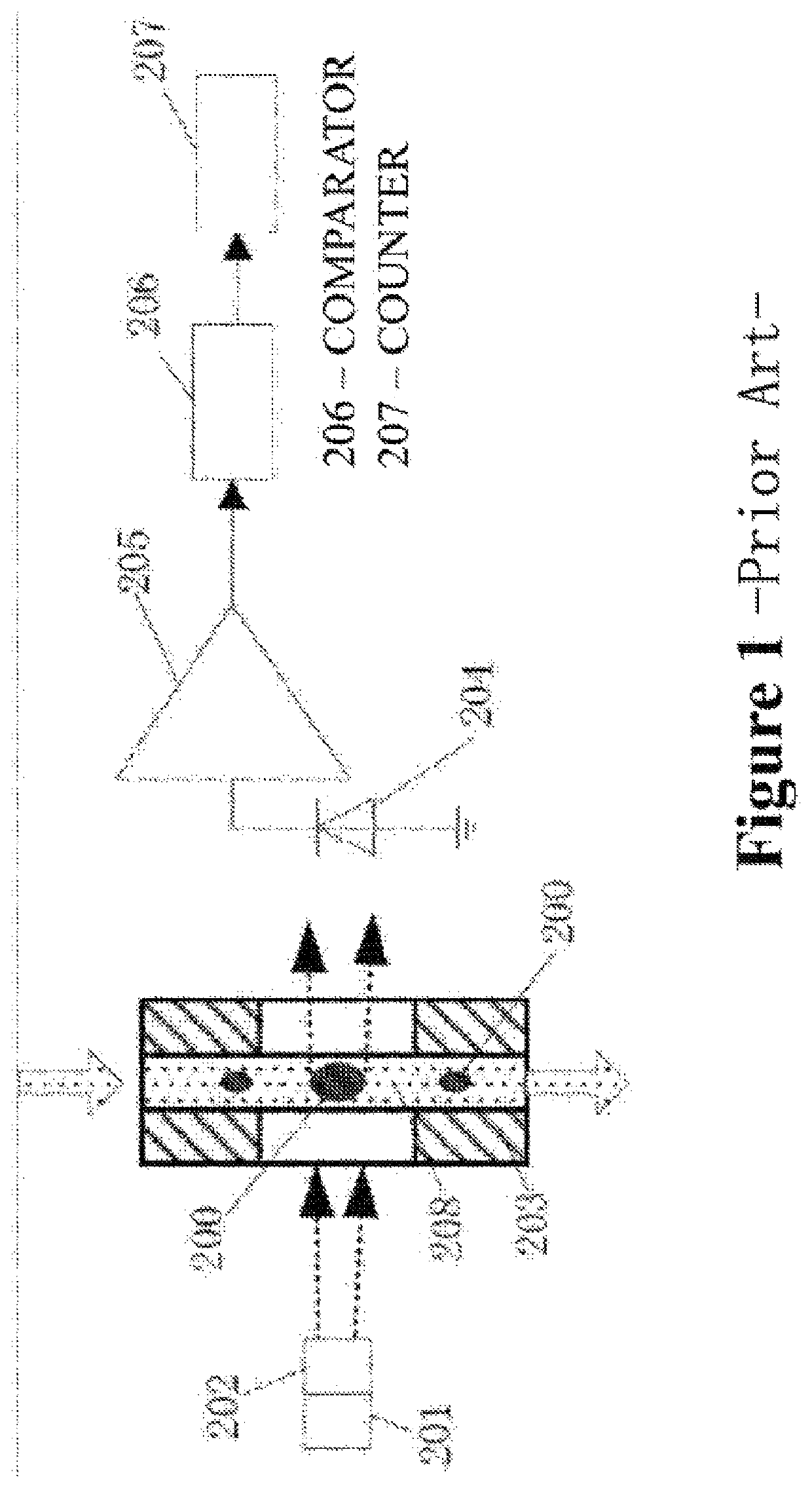
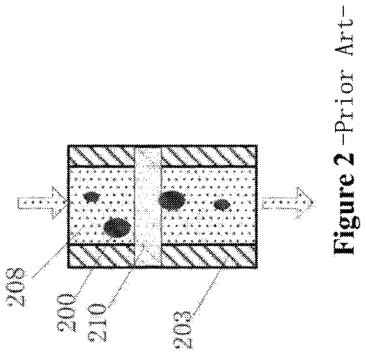
[0050]a flow cell module 2, the flow cell module 2 has a flow channel 21 through which the particles 100 flow, the light beam being irradiated on the flow channel 21 to form a light channel 101 at the flow channel 21 for detecting the particles 100;

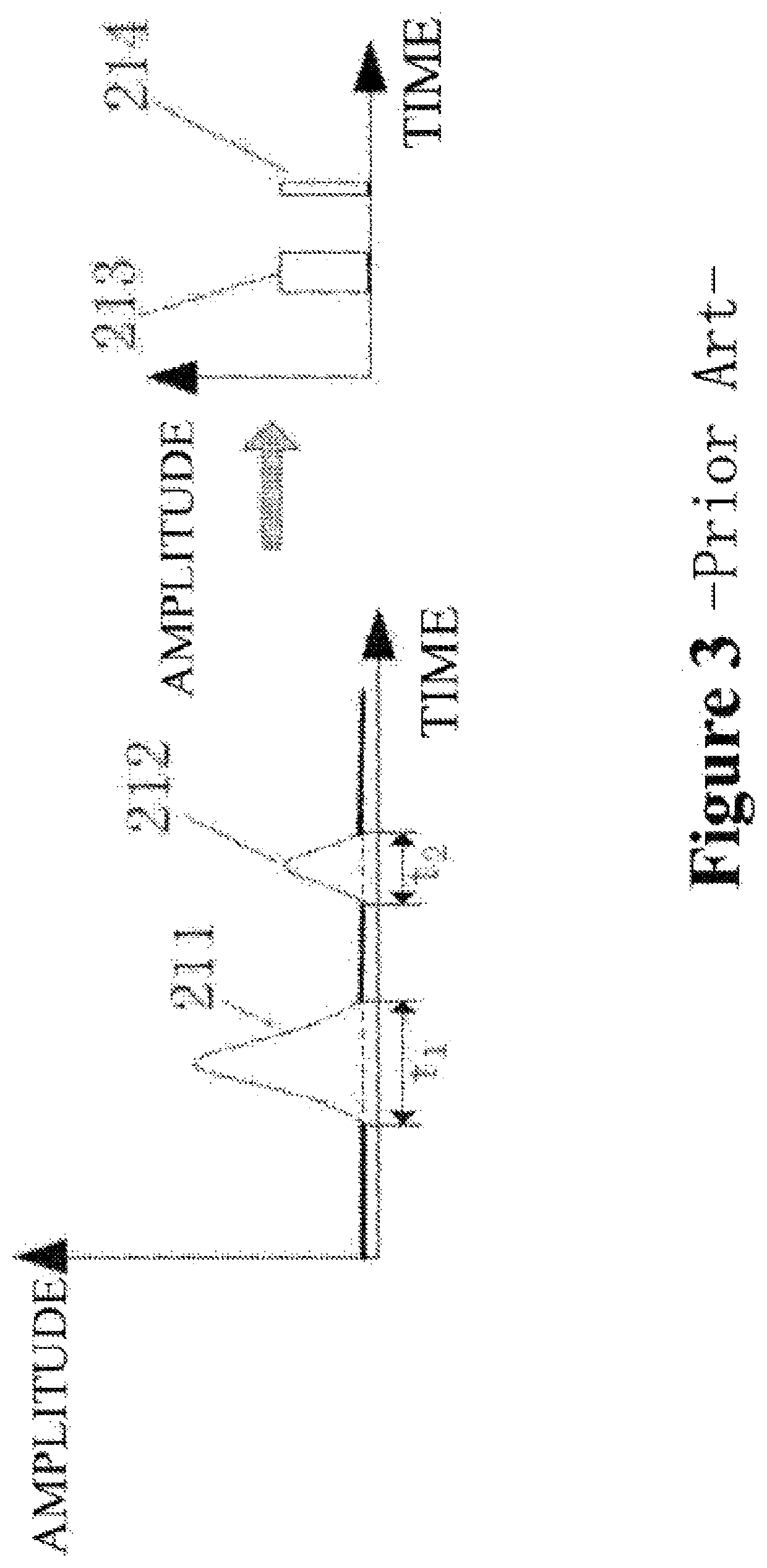
[0051]an optical signal collecting and processing module 3, the optical signal collecting and processing module 3 is configured to acquire scattered optical signals formed by the particles 100 passing through the light channel 101, to convert the scattered optical signals into corresponding pulse signals, to compensate the pulse signals, and to screen and count the pulse signals.

[0052]In the present embodiment, the light source module 1 comprises a semiconductor laser for generating a laser beam and a collimating lens disp...


PUM

PropertyMeasurementUnit
optical densityaaaaaaaaaa
optical density distribution functionaaaaaaaaaa
distanceaaaaaaaaaa

Abstract

The present disclosure relates to a particle counting method and system. The particle counting method, comprises: obtaining distances between positions closest to a centers of a light channel in paths along which particles pass through the light channel and the centers of the light channel; according to an optical density distribution of the light channel, compensating amplitudes of the pulse signals of the particles when passing through the positions closest to the centers of the light channel in the path along which the particles pass through the light channel such that the compensated amplitudes of the pulse signals of the particles are equal to amplitudes of pulse signals of the particles with the same particle diameters when passing through the centers of the light channel; screening and counting the particles according to the compensated amplitudes of the pulse signals to realize counting of particles with respective particle sizes.

Description

CROSS REFERENCE TO RELATED APPLICATION[0001]The present application claims the priority of Chinese patent application CN 201710235740.7, filed on Apr. 12, 2017, which is hereby incorporated herein by reference in its entirety.TECHNICAL FIELD OF THE INVENTION[0002]The present disclosure belongs to the field of particle optical detection, and in particular, relates to a particle counting method and system.BACKGROUND OF THE INVENTION[0003]Optical particle counters are currently the primary detection tool for most industrially controlled particle contamination. Classifying by particle sizes, particles includes 5 μm particles, 2 μm particles, 1 μm particles, 0.5 μm particles, 0.2 μm particles, 0.1 μm particles, 0.05 μm particles, and even smaller, nano-sized particles.[0004]Optical particle counters currently used to detect micron-sized particles (above 2 μm) are based on the principle of the light blockage method. As shown in FIGS. 1 and 2, the existing light-blockage particle counter c...

Claims


Application Information

Patent Timeline
Patent Type & Authority Patents(United States)
IPC IPC(8): G01N15/14
CPCG01N15/1434G01N2015/1486G01N15/14G01N15/1459G01N2015/1493G01N15/1429Y02A90/10
Inventor LIANG, FENGFEISUN, JIYONGSHEN, WEIDONGZHOU, DANONGCHEN, JIAN
Owner JIANGSU SUJING GROUP
Why Eureka
Try Eureka