Variable camber continuous aerodynamic control surfaces and methods for active wing shaping control

a continuous, aerodynamic control technology, applied in the field of aeronautics, can solve the problems of reducing span efficiency, adverse impacts on aerodynamic efficiency, and reducing span efficiency, so as to improve various performance metrics of air vehicles and reduce drag

Active Publication Date: 2020-09-29
NASA
View PDF6 Cites 3 Cited by
  • Summary
  • Abstract
  • Description
  • Claims
  • Application Information

AI Technical Summary

Benefits of technology

[0015]Various embodiments are directed at addressing drag reduction of air vehicles through elastic wing shaping control to improve various performance metrics of air vehicles. The multidisciplinary nature of flight physics is appreciated with the recognition of the adverse effects of aeroelastic wing shape deflections on aerodynamic drag. By aeroelastically tailoring the wing shape with active control, a significant drag reduction benefit may be realized.
[0016]To realize the potential of the elastic wing shaping control, some embodiments achieve the performance metrics improvement goal through a new type of aerodynamic control surfaces. Some embodiments achieve the performance metrics improvement goals by utilizing a multi-camber flap system that comprises one or more spanwise flap segments for each wing of an aircraft, and each of the one or more flap segments comprises multiple chordwise segments (e.g., at least two chordwise segments), each of which may be actuated independently of the others to accommodate various configurations for different maneuvers such as increased wing area for takeoff and climbing, increased lift for landing, increased aerodynamic efficiency during cruise or descent, increased drag and reduced lift for aerodynamic braking, and others.

Problems solved by technology

However, as the aircraft wings become flexible, potential adverse impacts on aerodynamic efficiency may exist.
Consequently, the span efficiency may decrease as the aircraft wings deflect significantly from the optimal wing shape at the design point.
This reduction in span efficiency therefore causes an increase in drag which may potentially negate the original goal of employing lightweight airframe design for drag reduction.
Thus, it is realized that there is an unfulfilled need to have an ability to improve aerodynamic efficiency and reduce drag of aircraft due to non-optimal wing shape in flight.

Method used


Image

  • Variable camber continuous aerodynamic control surfaces and methods for active wing shaping control
  • Variable camber continuous aerodynamic control surfaces and methods for active wing shaping control
  • Variable camber continuous aerodynamic control surfaces and methods for active wing shaping control

Examples


Embodiment Construction

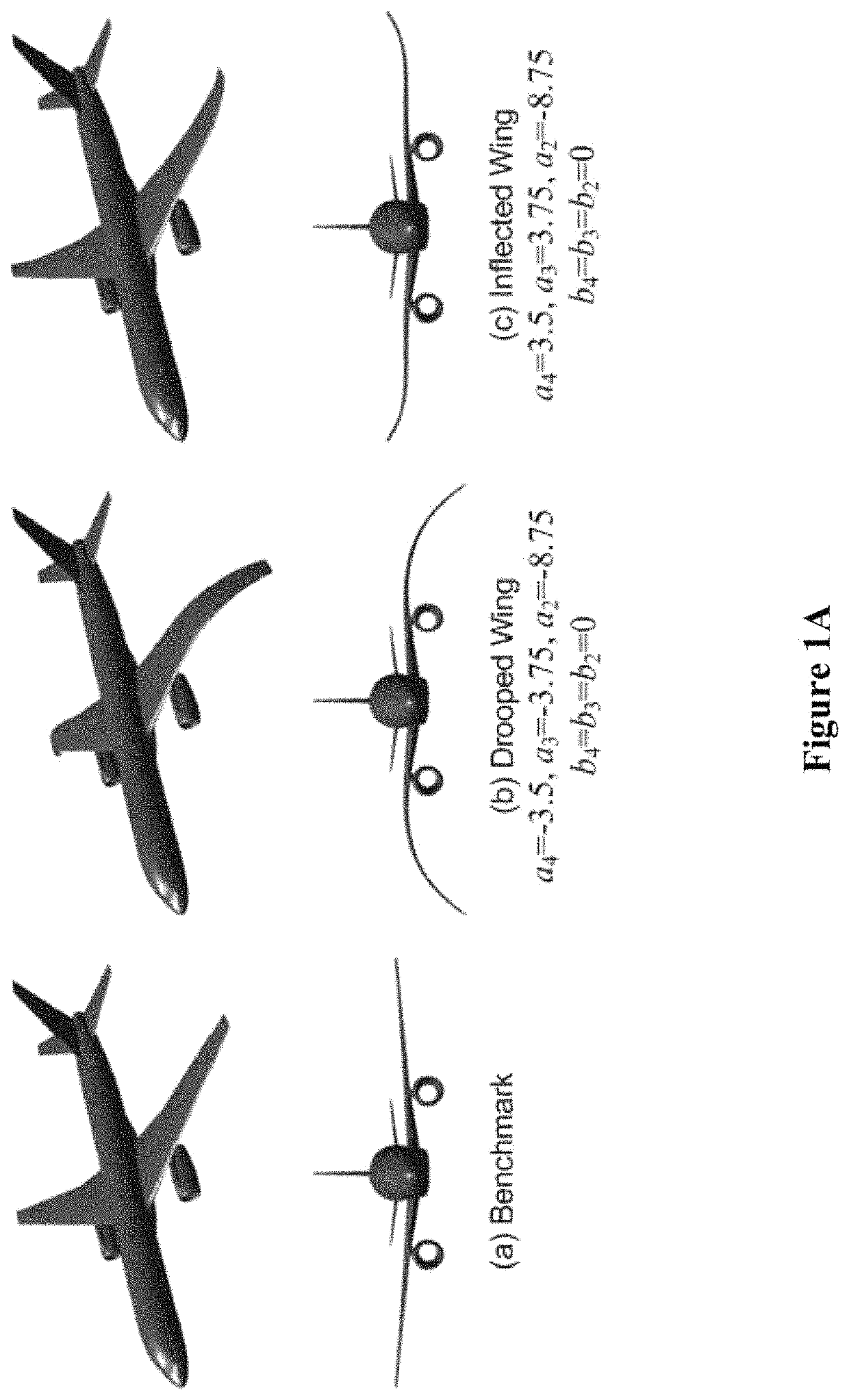
[0066]The “variable camber continuous aerodynamic control surfaces and methods for active wing shaping control” represent an innovative approach that helps realize the goal of drag reduction that may directly address the global challenge of improving aircraft fuel efficiency. This concept of “variable camber continuous aerodynamic control surfaces and methods for active wing shaping control” is a significant departure from a conventional design, but is firmly grounded in science, thus making it a revolutionized, yet realizable concept. Air vehicles are typically designed to maintain sufficient structural rigidity for safe load-carrying capacity. Moreover, the “variable camber continuous aerodynamic control surfaces and methods for active wing shaping control” provide a new capability to fully reconfigure a conventional fixed-geometry wing to enable such a wing equipped with the said variable camber continuous aerodynamic control surfaces to be aerodynamically and elastically adaptab...


PUM


Abstract

There is provided an aerodynamic control apparatus for an air vehicle comprising a flap system including a first spanwise flap segment to be arranged on a first side of an air vehicle, a second spanwise flap segment to be arranged on the first side of the air vehicle, and a controller to actuate the first spanwise flap segment to a first flap deflection and the second spanwise flap segment to a second flap deflection, wherein the first spanwise flap segment at the first flap deflection and the second spanwise flap segment at the second flap deflection form a piecewise continuous trailing edge.

Description

CROSS-REFERENCE TO RELATED APPLICATIONS[0001]This patent application is a divisional of U.S. patent application Ser. No. 13 / 648,197, filed on Oct. 9, 2012, now U.S. Pat. No. 9,227,721, issued Jan. 5, 2016, which claims the benefit of U.S. provisional patent application 61 / 628,299, filed Oct. 7, 2011 and entitled “Elastically Shaped Future Air Vehicle Concept,” each of which is incorporated in its entirety along with all other references cited in this application.ORIGIN OF INVENTION[0002]The invention described herein was made by an employee of the United States Government and may be manufactured and used by or for the Government of the United States of America for governmental purposes without the payment of any royalties thereon or therefor.BACKGROUND OF THE INVENTION[0003]This invention relates to the field of aeronautics and more specifically to enhancing the efficiency and performance of air vehicles.[0004]The National Aeronautics and Space Administration or NASA is a United Sta...

Claims


Application Information

Patent Timeline
Patent Type & Authority Patents(United States)
IPC IPC(8): B64C3/50B64C9/24B64C9/20B64C3/14B64C7/00B64C9/26
CPCB64C9/26B64C9/24B64C3/14B64C3/50B64C9/20B64C7/00B64C2003/147B64C3/48B64C3/52B64C2003/445B64C9/14Y02T50/10Y02T50/30Y02T50/40
Inventor NGUYEN, NHAN T.
Owner NASA
Why Eureka
Try Eureka