
Aircraft engine fuel system

Active Publication Date: 2015-04-09
ROLLS ROYCE PLC
View PDF4 Cites 6 Cited by
  • Summary
  • Abstract
  • Description
  • Claims
  • Application Information

AI Technical Summary

Benefits of technology

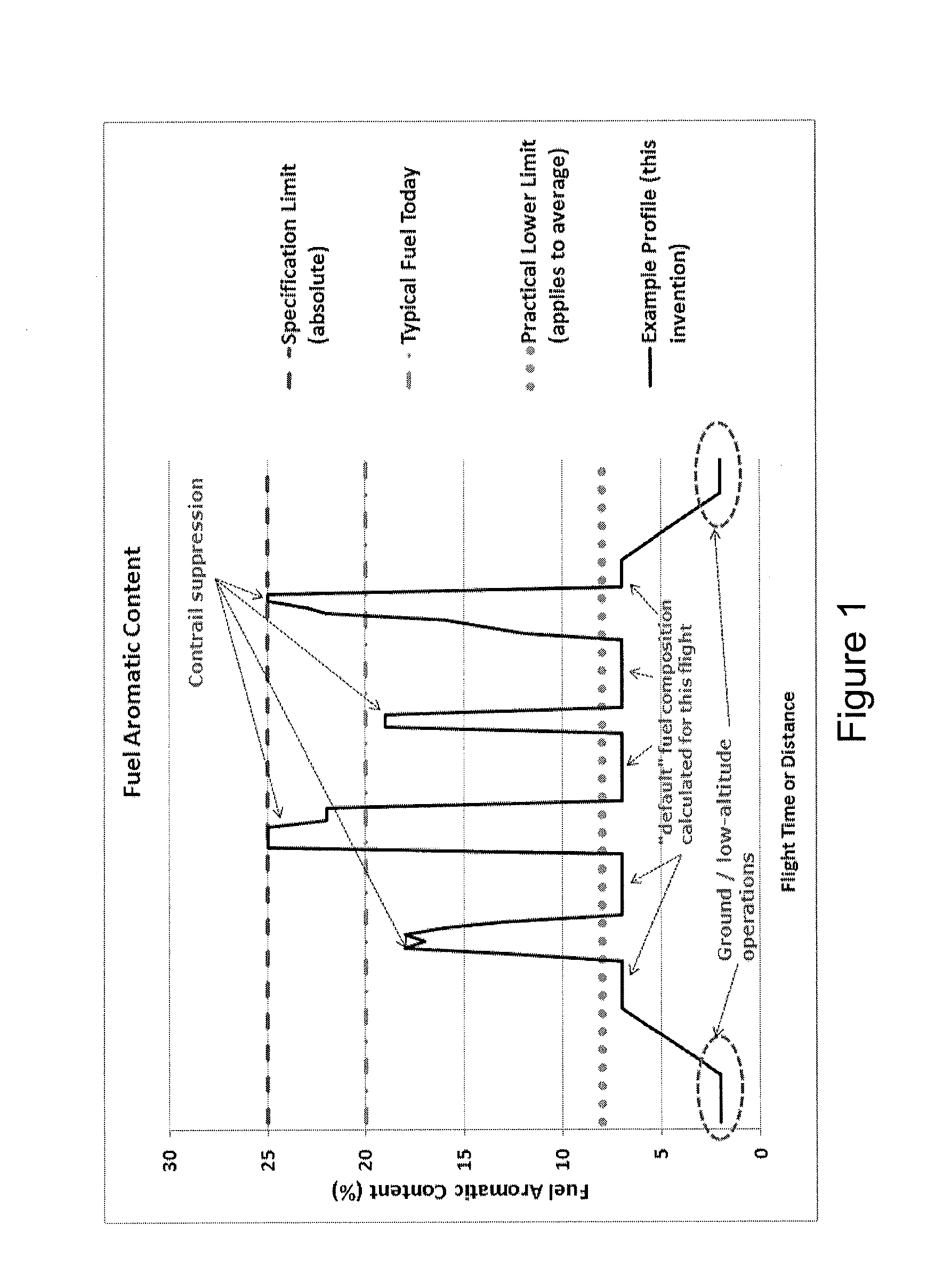
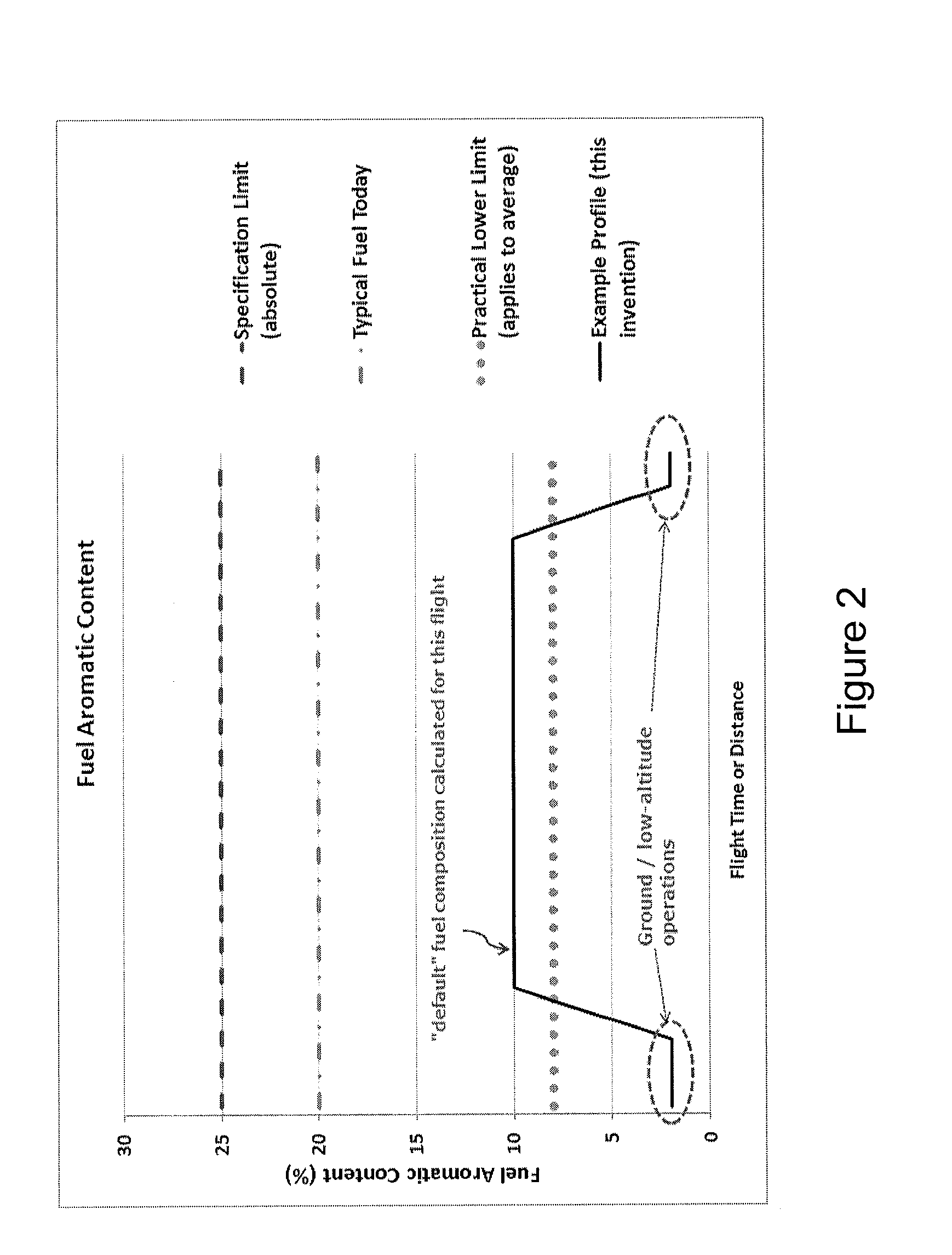
This invention provides a mechanism to increase the aromatic content of fuel burned by an engine to prevent contrails (clouds) from forming when there is no need for them. This allows for the use of low-aromatic fuel for most of the flight, resulting in improved fuel efficiency and reduced soot, while minimizing the impact on air quality. The invention controls the aromatic content of the fuel delivered to the engine based on predetermined thresholds to prevent exceeding the upper limit and achieves a reduced level of exhaust emissions during take-off and landing. The primary aim is contrail suppression, while the secondary aim is optimizing engine efficiency. The controller adjusts the aromatic content within the predetermined thresholds to achieve these aims without causing persistent contrails.

Problems solved by technology

It has been found that contrail formation may be affected by the properties of the fuel that is burned in the engine of an aircraft.
Although lower aromatic fuels may have a number of advantages over fossil kerosene, their incorporation into jet fuel nonetheless presents a problem regarding the susceptibility of an engine to the formation of contrails, since the lower aromatic content of the fuel means that the ratio of water-vapour-to-heat added by the engine to the exhaust plume is increased.
This enables the formation of contrails over a wider range of atmospheric conditions, resulting in increased prevalence of contrails.
Each of these methods may however result in a significant weight penalty for the engine.
Furthermore, the latter example would also need to draw power thereby reducing fuel efficiency and, particularly for military applications, the emission of electromagnetic radiation may have the undesirable effect of increasing aircraft detectability.
Other solutions include eliminating some or all contrail formation and / or persistence through routing aircraft around / above / below regions of air susceptible to contrail formation and / or persistence, yet such a solution results in a wide variety of further issues to be solved.
For example, rerouting of aircraft to avoid regions prone to contrail persistence may cause associated air traffic control complications as well as the increased fuel burn involved in climbing or otherwise increasing the distance travelled by an aircraft and / or flying at a non-optimal cruise altitude.

Method used


Image

  • Aircraft engine fuel system
  • Aircraft engine fuel system
  • Aircraft engine fuel system

Examples


first embodiment

[0082]A first embodiment involves the blending together, onboard the aircraft, of a number of distinct fluid compositions to produce a final fuel composition which is then supplied to the engines. The final fuel composition may at different times of the flight consist of i) exclusively any one of the distinct fluid compositions, or ii) a mixture of some or all the distinct fluid compositions.

[0083]In principle, in embodiment (ii) it is not required that each and every one of the distinct fluid compositions is compliant with applicable fuel-specifications, provided that the final fuel composition is at all times compliant. For instance, one of the distinct fluid compositions could be characterised by an aromatic content that lies above the maximum permitted level for use in an engine. Said fluid composition would then be used as an “additive” to one or more of the other fluid compositions in order to raise the aromatic content of the final fuel composition to the desired value, provi...

second embodiment

[0107]the invention will now be described, which does not involve blending of the fuels on board the aircraft. This embodiment has the advantage that the fuel system is simpler in that it involves the switching between the distinct fluid compositions available on the aircraft. This embodiment therefore requires that each of the distinct fluid compositions loaded into the aircraft be compliant with all fuel specifications, for example such that each fuel composition lies at or below the predetermined upper threshold for aromatic content.

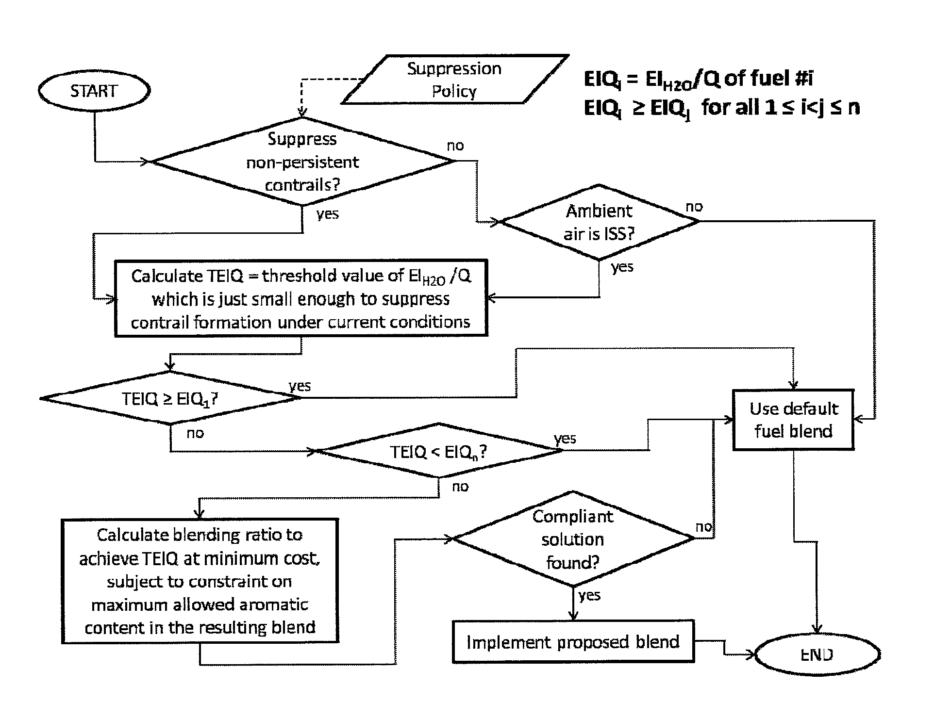
[0108]FIG. 5 illustrates an example of the decision making process required to identify which of the available fuel compositions should be employed according to the second embodiment. As with the first embodiment, the decision-making process is invoked whenever there is a material change in ambient conditions or in engine operating point.

[0109]Where the process is the same as described above, the stages will not be repeated for conciseness. The key di...

third embodiment

[0114]In a third embodiment, no fuel-blending or fuel-switching is performed on board the aircraft. As a result, there is no decision making to be performed on the aircraft and the aircraft engine can operate in a conventional manner. In this embodiment a determination of the composition of a single fuel type to be loaded onto the aircraft is made prior to a flight. The fuel composition will be tailored to one or any combination of the requirements of that particular flight; predetermined meteorological information for the flight path; historical data for the route, such as average requirements of the proposed route at the time of year or else operational data (e.g. contrail detection or suppression data) from a previous flight of the route.

[0115]FIG. 6 shows the aircraft-mounted fuel-system corresponding to the first embodiment. Within the diagram, solid arrows indicate the flow of fluid, while dashed arrows indicate the flow of data or instructions.

[0116]Distinct sources 20 and 22...


PUM


Abstract

This invention concerns a method of delivering fuel to an aircraft engine 60, which involves providing a plurality of distinct fuel sources 20, 22, a first fuel source 20 comprising a first fuel having a first aromatic content and a second fuel source 22 comprising a second fuel having a second aromatic content. One or more ambient atmospheric condition is determined for at least a portion of a flight path of the aircraft, said condition being indicative of a likelihood of contrail 135 formation by the engine 60. A desirous fuel composition for combustion by the engine is determined based upon the one or more ambient atmospheric condition and a ratio of the first and second fuels from said respective fuel sources is selected according to said desirous fuel composition. The selected ratio of the first and second fuels is delivered to the aircraft engine 60.

Description

BACKGROUND OF THE INVENTION[0001]The present invention relates to a fuel system, and more particularly a fuel system for aiding the prevention of the formation of contrails.[0002]Contrails, also known as condensation trails or vapour trails, are line-shaped ice-clouds that appear behind aircraft under certain circumstances. The formation of a contrail depends on a number of factors, including: ambient temperature, humidity and pressure; the efficiency of the aircraft's engines; and the properties of the fuel burned in the engines.[0003]A contrail, once formed, will typically dissipate within a minute or so, unless the ambient air is supersaturated with respect to ice, in which case the contrail may persist. A persistent contrail will grow over time to resemble natural cirrus cloud, both in size and optical properties, and is referred to as “contrail-cirrus”. Line-shaped contrails and contrail-cirrus are collectively referred to as “aviation-induced cloudiness” (AIC).[0004]It has bee...

Claims


Application Information

Patent Timeline
IPC IPC(8): F02C9/28F02C9/40
CPCF02C9/40F02C9/28F02C3/20F02C7/22F05D2270/08F05D2270/311F05D2270/312F05D2270/313Y02T50/60F02C9/26
Inventor SWANN, PETER
Owner ROLLS ROYCE PLC
Learn More