
Process for production of an olefin oxide

a technology of olefin oxide and epoxidation process, which is applied in the direction of catalyst activation/preparation, metal/metal-oxide/metal-hydroxide catalyst, molecular sieve catalyst, etc., can solve the problem of not teaching about the influence of pore size distribution on the catalyst performance, the process selectivity decreases, and the catalyst performance is not taught. problem, to achieve the effect of improving performance, increasing productivity, and reducing selectivity

Active Publication Date: 2009-03-05
SD LIZENZVERWGMBH
View PDF16 Cites 20 Cited by
  • Summary
  • Abstract
  • Description
  • Claims
  • Application Information

AI Technical Summary

Benefits of technology

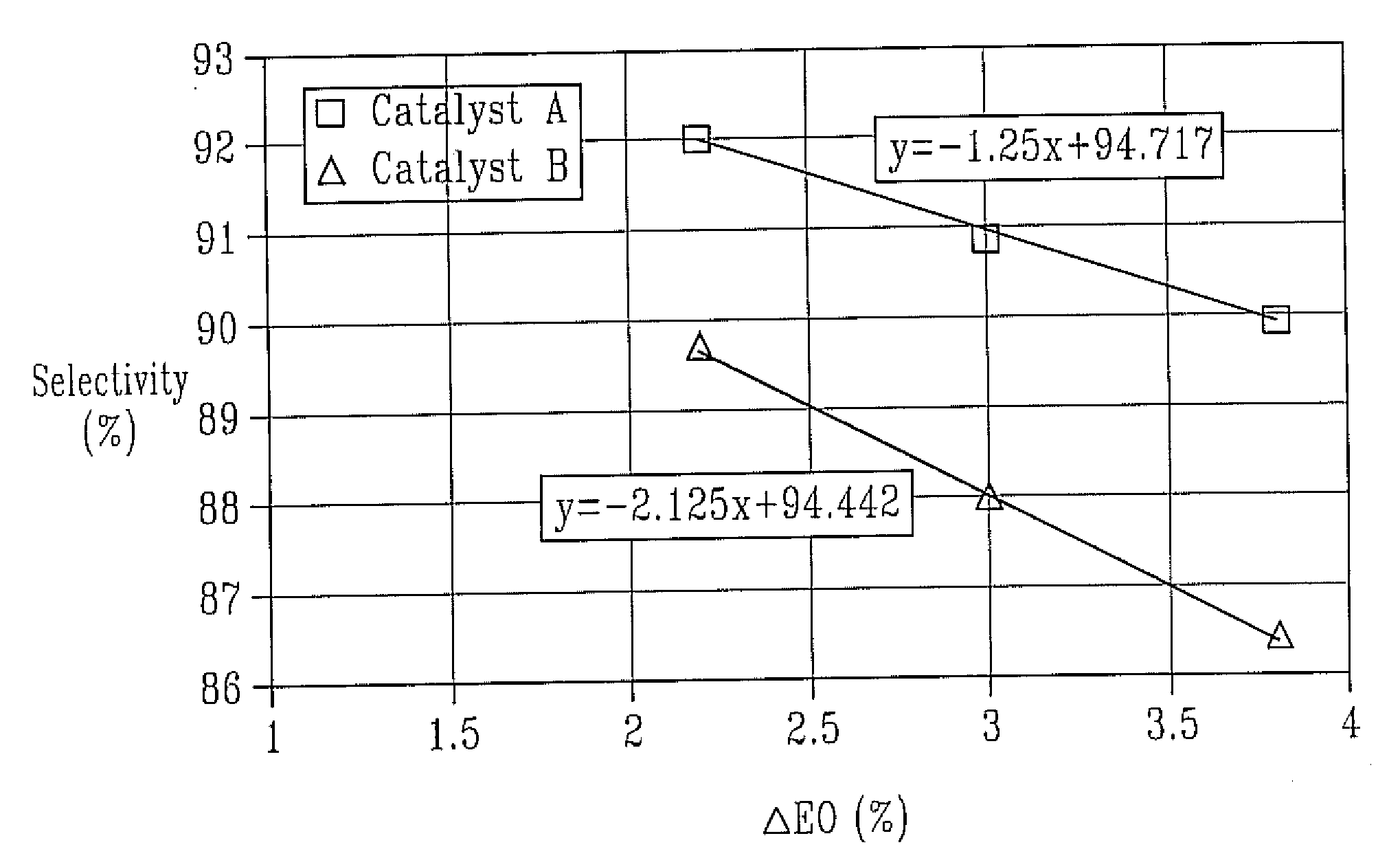
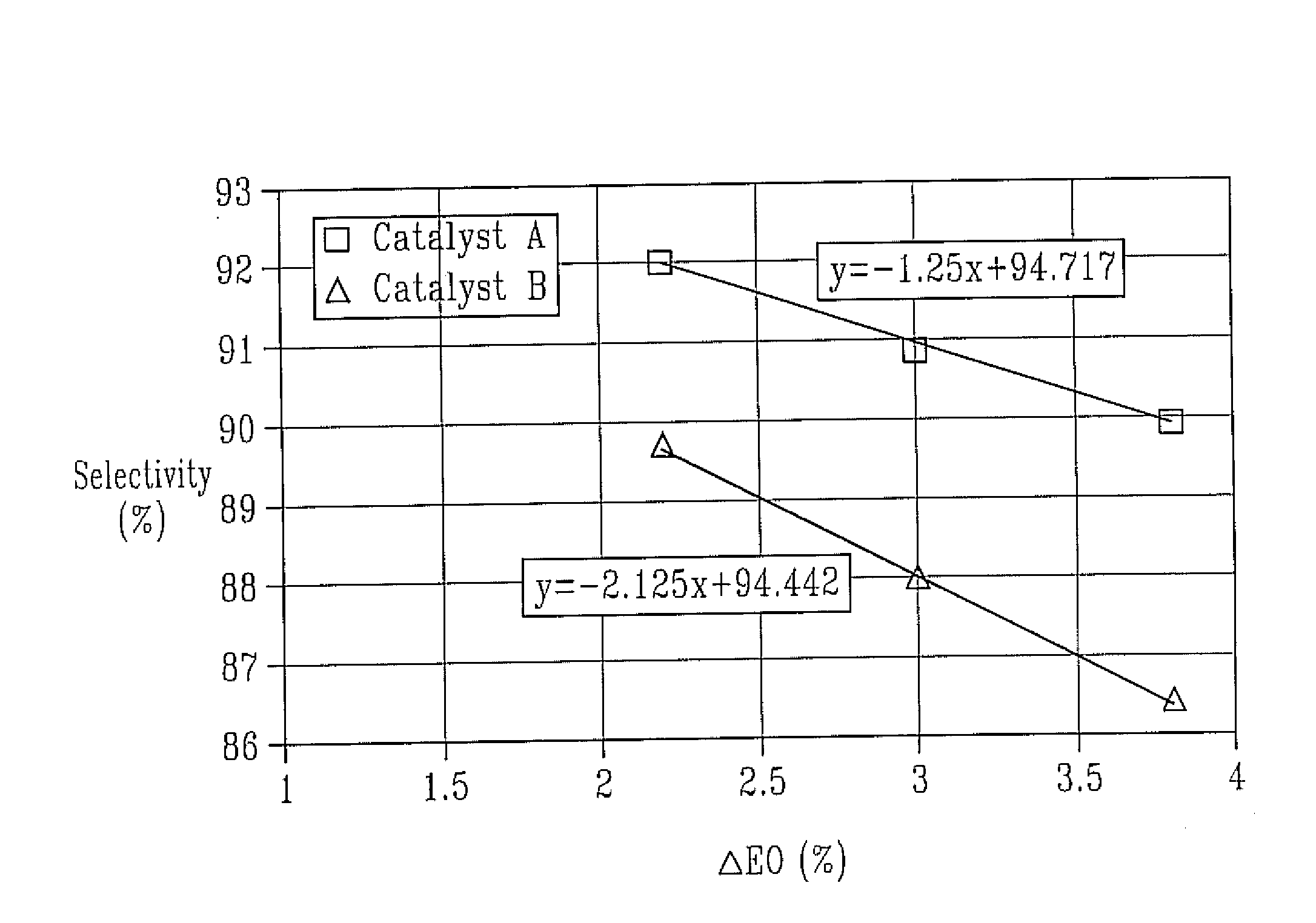
[0012]An increased productivity (expressed herein by the concentration of ethylene oxide in the reactor outlet gas) catalyst containing silver and rhenium supported by a carrier with a bimodal pore size distribution is provided that shows improved performance. The catalyst according to the invention shows a minor loss in selectivity at higher productivities whereas conventional catalysts with monomodal pore size distribution show a significant loss in selectivity at higher productivities.
[0016]In the present invention, the olefin oxide concentration in the reactor outlet is obtained by adjusting the olefin and oxygen conversion. That is, the olefin oxide concentration in the reactor is obtained by increasing the reaction temperature during the epoxidation reaction. An increase of the reaction temperature has always a negative effect on the catalyst selectivity. This decrease in catalyst selectivity is economically undesired and reduces the benefit of the higher productivity. The selectivity decrease can be significant, i.e., more points of selectivity for less than one point increase of the olefin oxide concentration in the reactor outlet. It was found, that catalysts according to the invention show only a minor selectivity decrease at higher productivities, i.e., higher olefin and oxygen conversion, and, therefore, have a significant economical benefit compared to state of the art catalysts.

Problems solved by technology

Since all olefin oxide plants have limited capability for increasing the flow rate because of the plant design, the most common procedure to increase the productivity is the adjustment of the olefin oxide concentration in the reactor outlet.
However, by increasing the level of olefin oxide in the reactor outlet, the selectivity of the process decreases significantly which counteracts the desired productivity increasing.
However, the disclosure of the '647 publication does not teach about the influence of the pore size distribution on the catalyst performance at high productivities.
It has now been found that the physical characteristics of the finished catalyst and the impact of the characteristics on the catalyst performance are more complicated than heretofore believed, especially if the catalyst is promoted with rhenium.

Method used


Image

  • Process for production of an olefin oxide
  • Process for production of an olefin oxide

Examples


example 1

Catalyst A

[0056]A 150 g portion of alumina support A was placed in a flask and evacuated to approximately 0.1 torr prior to impregnation. To the above silver solution aqueous solutions of cesium hydroxide, perrhenic acid, and ammonium sulfate were added in order to prepare a catalyst composition according to examples 3-10 through 7-20 of U.S. Pat. No. 4,766,105. After thorough mixing, the promoted silver solution was aspirated into the evacuated flask to cover the carrier while maintaining the pressure at approximately 0.1 torr. The vacuum was released after about 5 minutes to restore ambient pressure, hastening complete penetration of the solution into the pores. Subsequently, the excess impregnation solution was drained from the impregnated carrier. Calcination of the wet catalyst was done on a moving belt calciner. In this unit, the wet catalyst is transported on a stainless steel belt through a multi-zone furnace. All zones of the furnace are continuously purged with pre-heated,...

example 2

Catalyst B (Comparative Example)

[0058]Catalyst B was prepared with alumina support B following the procedure of Catalyst A.

[0059]Testing of the Catalyst

[0060]For testing, the catalyst was charged into a fixed-bed stainless steel tube reactor (¼ inch approximate inner diameter), which was embedded in a heated copper block. The catalyst charge consisted of 12 g crushed catalyst (1.0-1.4 mm particle size) and the inlet gas flow was adjusted to 0.75 Nl / min. The feed gas composition by volume was 25% ethylene, 7% oxygen, 2% carbon dioxide, 0.5-5 ppmv ethyl chloride, and nitrogen ballast. Reaction pressure was maintained at 300 psig. The reactor effluent was analyzed by mass spectrometry at roughly 1-hour intervals.

[0061]The feed gas was introduced at 200° C. and increased by 1° C. / h until the EO concentration in the reactor outlet reached 3.8% by volume. The ethyl chloride concentration in the inlet gas was adjusted until the maximum selectivity was achieved. Subsequently, the EO concent...


PUM

PropertyMeasurementUnit
mean diameteraaaaaaaaaa

Abstract

The invention relates to a process for the epoxidation of an olefin, wherein the concentration of the olefin oxide in the outlet is greater than about 2.2% by volume. More particularly, the invention relates to a process for the epoxidation of ethylene by contacting a feed including at least ethylene and oxygen with an improved epoxidation catalyst. The catalyst which has improved selectivity in the epoxidation process at high productivities, includes a solid support having a surface, which has a first mode of pores that have a diameter ranging from about 0.01 μm to about 5 μm and having a differential pore volume peak in the range from about 0.01 μm to about 5 μm. The surface also has a second mode of pores, which is different from the first mode of pores, having a diameter ranging from about 1 μm to about 20 μm and have a differential pore volume peak in the range from about 1 μm to about 20 μm. On the bimodal pore surface is a catalytically effective amount of silver or a silver-containing compound, a promoting amount of rhenium or a rhenium-containing compound, and a promoting amount of one or more alkali metals or alkali-metal-containing compounds.

Description

FIELD OF THE INVENTION[0001]The present invention pertains to a process for the epoxidation of an olefin to an olefin oxide by contacting a feed gas comprising an olefin and oxygen with a catalyst comprising a silver compound and a rhenium compound deposited on a carrier with bimodal pore size distribution, wherein the concentration of the olefin oxide in the reactor outlet is greater than about 2.2% by volume. More particularly, the invention pertains to an improved catalyst useful for the epoxidation of ethylene to ethylene oxide at high catalyst work rates.DESCRIPTION OF THE RELATED ART[0002]Generally, commercially practiced olefin epoxidation is carried out by continuously contacting a feed gas comprising oxygen and an olefin with a catalyst under defined operating conditions. The resulting product mixture of olefin oxide and typically un-reacted oxygen and olefin as well as the total combustion products undergoes a separation procedure wherein the un-reacted feed gas components...

Claims


Application Information

Patent Timeline
Patent Type & Authority Applications(United States)
IPC IPC(8): C07D301/10C07D301/03
CPCB01J21/04B01J23/688B01J37/0203B01J35/1038B01J35/109B01J35/1009C07D301/10B01J35/612B01J35/633B01J35/69
Inventor GUECKEL, CHRISTIAN J.
Owner SD LIZENZVERWGMBH
Learn More