

Process for production of an olefin oxide
a technology of olefin oxide and epoxidation process, which is applied in the direction of catalyst activation/preparation, metal/metal-oxide/metal-hydroxide catalyst, molecular sieve catalyst, etc., can solve the problem of not teaching about the influence of pore size distribution on the catalyst performance, the process selectivity decreases, and the catalyst performance is not taught. problem, to achieve the effect of improving performance, increasing productivity, and reducing selectivity
- Summary
- Abstract
- Description
- Claims
- Application Information
AI Technical Summary
Benefits of technology
Problems solved by technology
Method used
Image

Examples
example 1
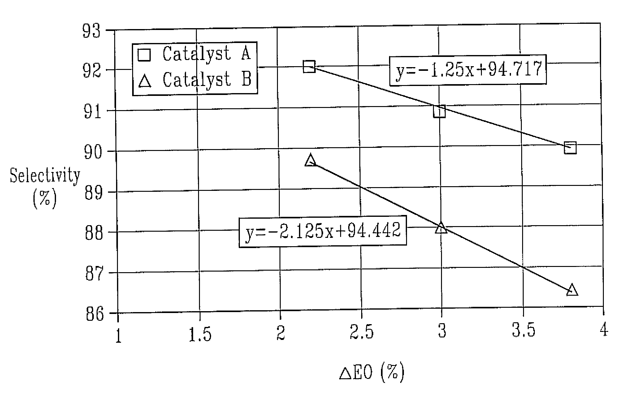
Catalyst A
[0057]A 150 g portion of alumina support A was placed in a flask and evacuated to approximately 0.1 torr prior to impregnation. To the above silver solution aqueous solutions of cesium hydroxide, perrhenic acid, and ammonium sulfate were added in order to prepare a catalyst composition according to examples 3-10 through 7-20 of U.S. Pat. No. 4,766,105. After thorough mixing, the promoted silver solution was aspirated into the evacuated flask to cover the carrier while maintaining the pressure at approximately 0.1 torr. The vacuum was released after about 5 minutes to restore ambient pressure, hastening complete penetration of the solution into the pores. Subsequently, the excess impregnation solution was drained from the impregnated carrier. Calcination of the wet catalyst was done on a moving belt calciner. In this unit, the wet catalyst is transported on a stainless steel belt through a multi-zone furnace. All zones of the furnace are continuously purged with pre-heated,...
example 2
Catalyst B (Comparative Example)
[0059]Catalyst B was prepared with alunina support B following the procedure of Catalyst A.
[0060]Testing of the Catalyst
[0061]For testing, the catalyst was charged into a fixed-bed stainless steel tube reactor (¼ inch approximate inner diameter), which was embedded in a heated copper block. The catalyst charge consisted of 12 g crushed catalyst (1.0-1.4 mm particle size) and the inlet gas flow was adjusted to 0.75 Nl / min. The feed gas composition by volume was 25% ethylene, 7% oxygen, 2% carbon dioxide, 0.5-5 ppmv ethyl chloride, and nitrogen ballast. Reaction pressure was maintained at 300 psig. The reactor effluent was analyzed by mass spectrometry at roughly 1-hour intervals.
[0062]The feed gas was introduced at 200° C. and increased by 1° C. / h until the EO concentration in the reactor outlet reached 3.8% by volume. The ethyl chloride concentration in the inlet gas was adjusted until the maximum selectivity was achieved. Subsequently, the EO concent...
PUM
| Property | Measurement | Unit |
|---|---|---|
| mean diameter | aaaaa | aaaaa |
| mean diameter | aaaaa | aaaaa |
| mean diameter | aaaaa | aaaaa |
Abstract
Description
Claims
Application Information