
Fluorescence imaging scope with reduced chromatic aberration

a fluorescence imaging and scope technology, applied in the field of endoscope design, can solve the problems of difficult to construct a single camera head capable of compensating for a variety of endoscope models, chromatic errors that are not typically designed to maintain a constant focus, and difficulty in enhancing so as to improve the chromatic correction, improve the entire spectrum, and enhance the use of endoscopes with fi

Active Publication Date: 2020-10-20
KARL STORZ IMAGING INC
View PDF7 Cites 2 Cited by
  • Summary
  • Abstract
  • Description
  • Claims
  • Application Information

AI Technical Summary

Benefits of technology

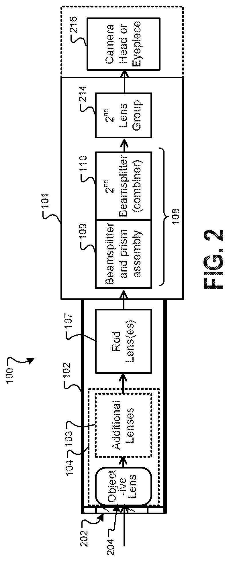
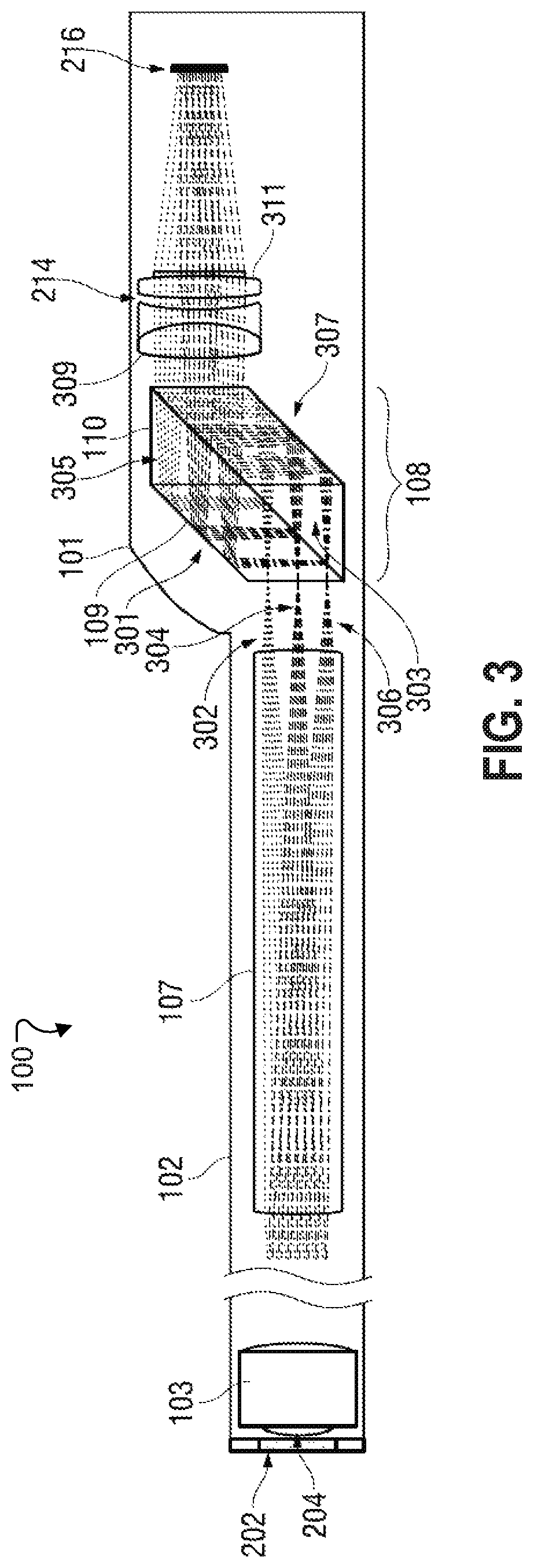
The invention aims to improve the correction of an entire spectrum of light from deep blue to infrared. To achieve this, the patent introduces various aspects of an improved fluoresced imaging (FI) endoscope device and system that enhance the use of endoscopes with FI and visible light capabilities. Specifically, a chromatic adjustment assembly is implemented with prisms, which compensates for a chromatic focal difference between a white light image and a fluoresced light image caused by the dispersive properties of the optical materials or optical design of the endoscope. The assembly is placed optically between the endoscope's most proximal rod lens and the focusing optics to improve chromatic correction. The prism assembly directs incoming light with different spectral content along separate paths which compensate for chromatic aberration. In summary, the patent provides a solution for better correction of the entire spectrum of light in the endoscope, which could ultimately enhance the quality and accuracy of medical procedures.

Problems solved by technology

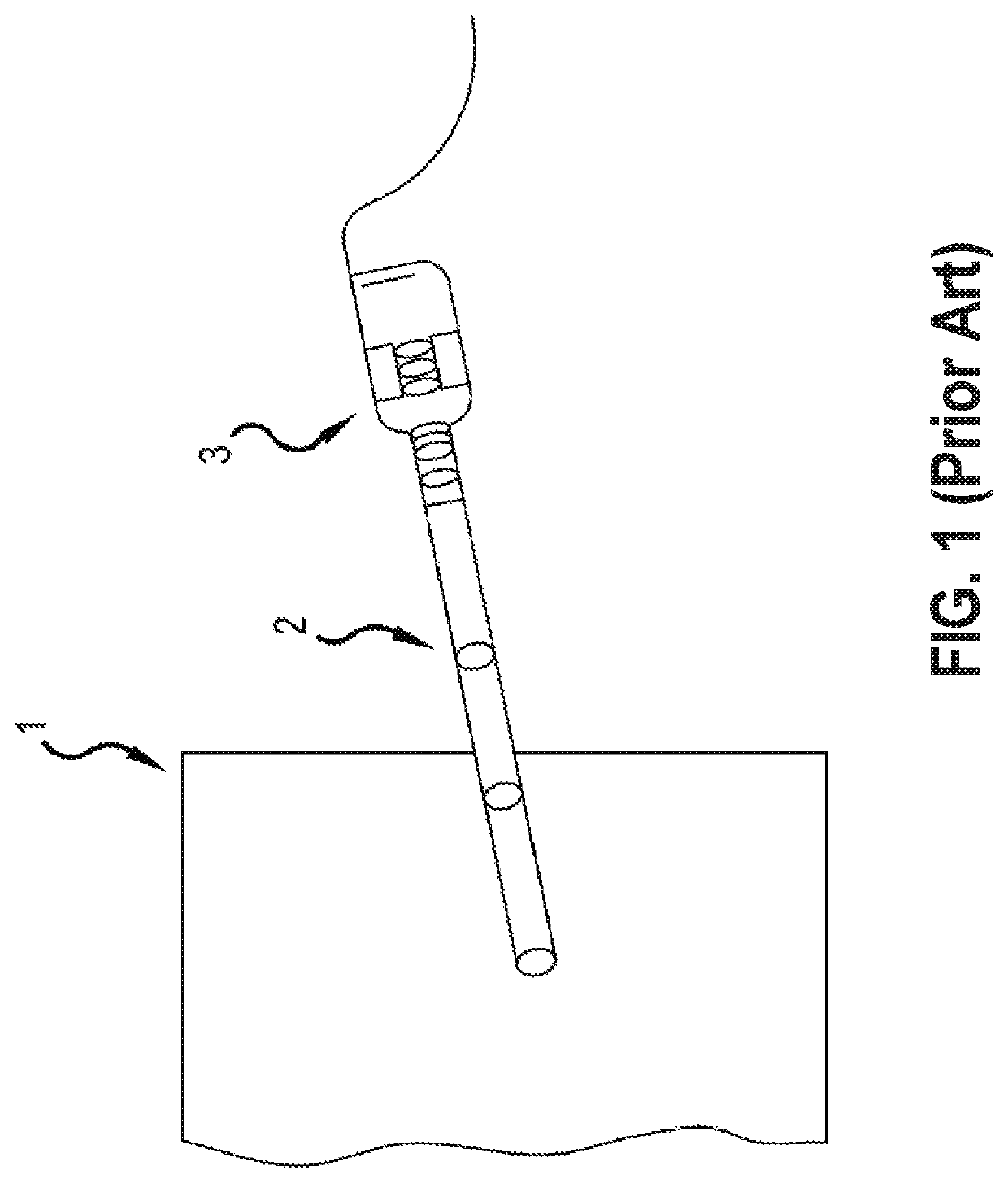
As such, they are not typically designed to maintain a constant focus between infrared light and visible light.
This approach is disadvantageous not only due to the complexity and cost of using multiple image sensors, but also in that various models of endoscopes will have varying amounts of chromatic error, requiring many configurations of camera head designs.
It is very difficult to construct a single camera head capable of compensating for a variety of endoscope models.
However, such systems still fail to compensate for the variety of chromatic aberrations across the desired spectrum, or to compensate for differences between various endoscopes.
The dispersive properties of the optical materials used in endoscopes, and long glass paths through such optical materials, make conventional correction of the entire spectrum from deep blue to infrared particularly difficult.
Techniques that using lenses or prisms to correct for longitudinal chromatic aberration often introduce unwanted lateral chromatic aberration.

Method used


Image

  • Fluorescence imaging scope with reduced chromatic aberration
  • Fluorescence imaging scope with reduced chromatic aberration
  • Fluorescence imaging scope with reduced chromatic aberration

Examples


Embodiment Construction

[0026]As used herein, first elements (e.g., sensors and lenses) that are “optically arranged” in relation to other elements, refers to the first elements' position along a common optical path that includes first and other elements. For example, a lens group optically arranged between an image sensor and an objective, means that the lens group occupies a portion of the optical path that light travels (e.g., from the objective to the image sensor) for capturing images or video.

[0027]Because digital cameras and FI sensors and related circuitry for signal capture and processing are well-known, the present description will be directed in particular to elements forming part of, or cooperating more directly with, a method and apparatus in accordance with the invention. Elements not specifically shown or described herein are selected from those known in the art. Certain aspects of the embodiments to be described are provided in software. Given the system as shown and described according to ...


PUM


Abstract

Improved fluoresced imaging (FI) endoscope devices and systems are provided to enhance use of endoscopes with FI and visible light capabilities. An endoscope device is provided for endoscopy imaging in a white light and a fluoresced light mode. A chromatic adjustment assembly, typically implemented with prisms, compensates for a chromatic focal difference between the white light image and the fluoresced light image caused by the dispersive properties of the optical materials or optical design employed in the construction of the optical channel. The assembly is placed optically between the most proximal rod lens of the endoscope and the focusing optics, typically at an internal telecentric image space, to improve the chromatic correction. The prism assembly directs incoming light with different spectral content along separate paths which compensate for chromatic aberration.

Description

TECHNICAL FIELD OF THE INVENTION[0001]The invention relates generally to the field of medical image capture and more specifically to endoscope designs for improving performance fluorescent imaging and visible color imaging.BACKGROUND OF THE INVENTION[0002]Endoscopes and other medical scopes often use fluorescing agents or autofluorescence to better examine tissue. A fluorescing agent such as a dye may be injected or otherwise administered to tissue, and then an excitation light is directed toward the tissue. Responsive to the excitation light, the fluorescing agent fluoresces (emits light typically at a longer wavelength than the excitation light), allowing a sensor to detect the light, which is often not in a wavelength visible to the human eye. The detected light is formatted to images, and examining the images can indicate the concentration of fluorescing agent in the observed tissue. Further, a phenomenon known as autofluorescence may occur in which tissue fluoresces light under...

Claims


Application Information

Patent Timeline
Patent Type & Authority Patents(United States)
IPC IPC(8): A61B5/00A61B1/002A61B1/04G02B21/00G02B23/24A61B1/055A61B1/00A61B1/05A61B1/06
CPCA61B5/0035A61B1/055A61B1/0653A61B1/043A61B1/00096A61B1/0638G02B21/0032A61B1/0019G02B23/2453A61B5/0071A61B1/053A61B5/0086G02B21/0064A61B1/002A61B1/046
Inventor DUCKETT, III, GEORGE E.
Owner KARL STORZ IMAGING INC
Learn More