
Device for transmitting a movement and a force between two zones that are insulated from one another

a technology of transmission device and transmission element, applied in the field of microelectronics, can solve the problems of limited or even nullified in-plane movement, and achieve the effect of reducing the energy transmission in the movement apart from the rotational movement in the transmission, small resistance to the movement of the transmission element, and reducing the amount of translational movement in the off-plan

Active Publication Date: 2020-10-20
COMMISSARIAT A LENERGIE ATOMIQUE ET AUX ENERGIES ALTERNATIVES
View PDF8 Cites 2 Cited by
  • Summary
  • Abstract
  • Description
  • Claims
  • Application Information

AI Technical Summary

Benefits of technology

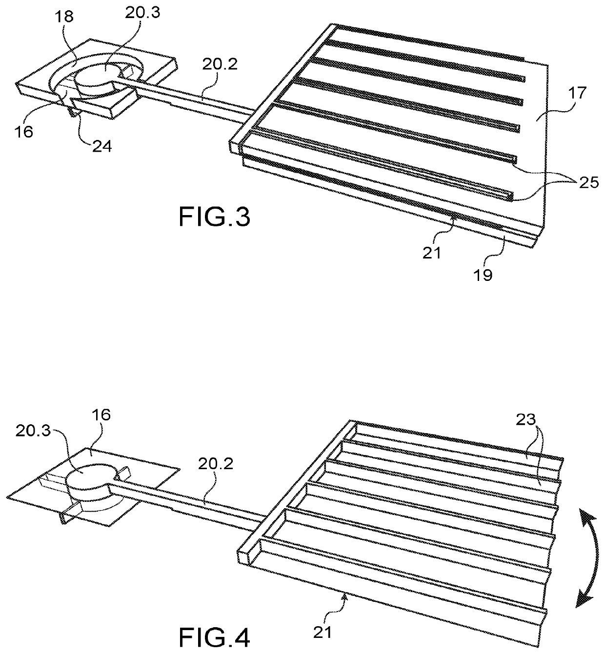
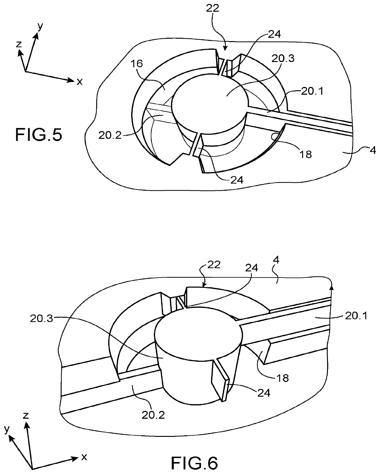
[0027]Since the transmission element has a rotational movement, its off-plane translational movements are substantially reduced, or even nullified. Advantageously, the rotational hinge is made by torsionally deformable arms which significantly limit, or even prevent the translational movement in an off-plane direction of the transmission element. The energy transmission in the movements apart from the rotational movement in the transmission is thereby reduced. By using deformable arms having a rectangular cross-section the off-plane dimension of which is strongly higher than the in-plane dimension, a rotational hinge having a low angular stiffness can be obtained, and thus very small energy losses can be achieved during the rotational movement. Further, the in-plane movements are limited, or even nullified, by the sealed insulation means. The mechanical efficiency of the transmission device is thus high.
[0028]Advantageously, one of the zones can be a controlled atmosphere chamber, advantageously a vacuum chamber, in which capacitive measurement means of the movement transmitted to the transmission element, and / or capacitive motors creating a force to be transmitted by the transmission element are provided. These capacitive means can thereby have a large electrode area without the viscous friction opposing to the movement of a part of said capacitive means.
[0029]Further, because of the nullification of the off-plane movements, in the case of a microphone, the effect of the atmospheric pressure on the measurement of the capacitive means is thereby substantially reduced, or even nullified. Therefore, the device measures only or nearly only the variation in acoustic pressure.

Problems solved by technology

Further, the in-plane movements are limited, or even nullified, by the sealed insulation means.

Method used


Image

  • Device for transmitting a movement and a force between two zones that are insulated from one another
  • Device for transmitting a movement and a force between two zones that are insulated from one another
  • Device for transmitting a movement and a force between two zones that are insulated from one another

Examples


Embodiment Construction

[0071]In the present application, a microelectronic system comprises one or more devices of the microelectromechanical system type and / or one or more devices of the nanoelectromechanical system type.

[0072]In the description that follows, the device will be described in an application to microphones, but this application is not restrictive and other exemplary applications will be given in the following.

[0073]The terms “upper” and “lower” and “on” and “below” are used to describe locations within the context of the representations of the drawings and are in no way limiting.

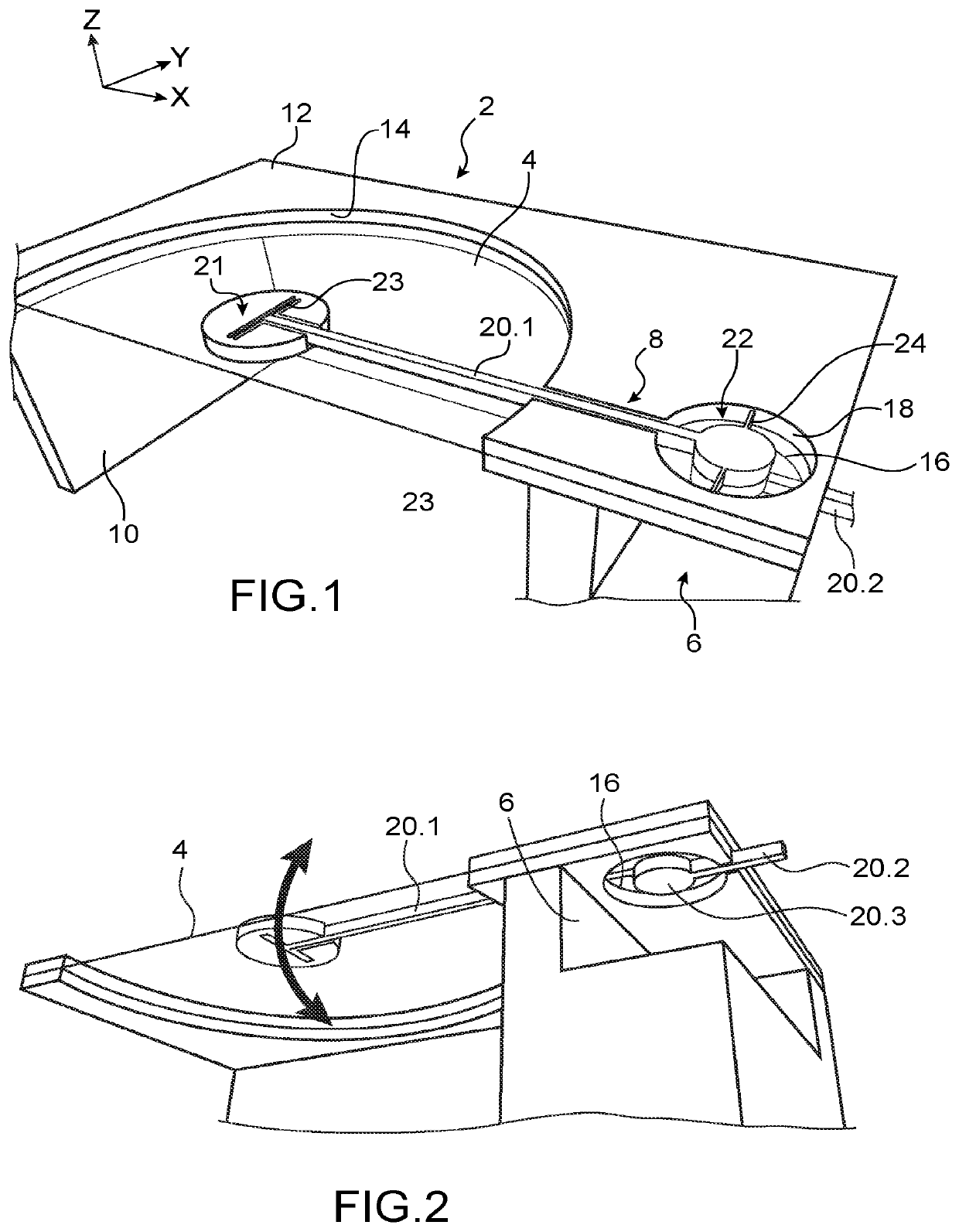
[0074]In FIGS. 1 to 6, an exemplary embodiment of a device according to the invention that can form a microphone can be seen.

[0075]The measurement chamber 6 is defined by the plate, the support and a sealed insulation element 16 such that the internal environment of the measurement chamber is insulated.

[0076]The device comprises a package 2, a measurement membrane 4 in contact with the external environment a variati...


PUM


Abstract

A device transmits a movement and a force between a first zone and a second zone which are insulated from one another in a sealed manner. The device includes a planar support, a transmission element that is rotatably movable with respect to the support by a pivot joint having an axis of rotation that is parallel to a plane of the support, an opening in the support through which the transmission element passes and level with which the pivot joint is positioned. The transmission element includes at least one first transmission arm on one side of the plane of the support and one second transmission arm on the other side of the plane of the support, and sealed insulation positioned in the opening, such that it insulates the first zone from the second zone in a sealed manner and allows the rotational movement of the transmission element.

Description

TECHNICAL FIELD AND STATE OF PRIOR ART[0001]The present invention relates to a device for transmitting a movement and a force between two zones sealingly separated from each other in the field of microelectronics and in particular that of micro-devices of the microelectromechanical system (MEMS) and / or nanoelectromechanical system (NEMS) type. Such a device can for example be implemented in a device for measuring a pressure variation, for example to make a microphone or in a pressure sensor.[0002]Microphones in microelectromechanics and / or in nanoelectromechanics represent a growing market, in particular by virtue of the market of mobile apparatuses, such as tablet computers, smartphone type portable telephones and other connected objects, in which they gradually replace electret microphones.[0003]Microphones measure a pressure variation, therefore they comprise at least one part in contact with the external environment.[0004]Most MEMS microphones currently produced are capacitive d...

Claims


Application Information

Patent Timeline
Patent Type & Authority Patents(United States)
IPC IPC(8): H04R25/00B81B3/00H04R19/02H04R19/04H04R31/00
CPCH04R19/04B81B3/0021H04R19/02H04R31/00B81B2201/0264B81B2201/0257B81B2203/058B81B2201/037B81B2203/0127B81B2203/051H04R2201/003B81B2203/04
Inventor JOET, LOIC
Owner COMMISSARIAT A LENERGIE ATOMIQUE ET AUX ENERGIES ALTERNATIVES
Learn More