Turbine blade cooling

a turbine blade and cooling technology, applied in the direction of blade accessories, engine fuctions, machines/engines, etc., can solve the problems of reducing the efficiency of the turbine assembly, reducing efficiency, and reducing the total loss of the turbine assembly by 30% or more, so as to achieve greater cooling, more film cooling channels, and greater flexibility in the arrangement of film cooling channels

Active Publication Date: 2020-11-03
ROLLS ROYCE PLC
View PDF20 Cites 0 Cited by
  • Summary
  • Abstract
  • Description
  • Claims
  • Application Information

AI Technical Summary

Benefits of technology

[0013]Conveniently, the gallery channel may be integrally cast into the blade using an adapted core which defines both the main trailing edge cooling channel and has an extension defining the gallery channel. Since the gallery channel is cast into the blade, there is no need for an additional operation to close the end of a drilled gallery channel. Also, since the gallery channel is defined by the core, it is possible to enlarge a portion of the gallery channel adjacent the main trailing edge cooling channel. This allows more surface area of the gallery channel wall in which to provide film cooling channels. Thus there is greater flexibility in the arrangement of film cooling channels and the possibility for more film cooling channels (and hence greater cooling) than is obtainable with prior art arrangements. The arrangement further provides for weight reduction in this area versus the prior art arrangement.
[0014]The gallery channel may be provided in a shape which minimises flow restriction in the gallery channel. For example the gallery channel is conically tapered from its open end to its closed end. In more complex embodiments, the cross sectional shape of the gallery channel may be varied in a manner designed to tune coolant flow to suit cooling requirements in different regions of the blade tip and squealer. For example, the gallery channel is shaped to encourage optimum flow rates to the film cooling holes in accordance with cooling requirements at the exits of the film cooling holes. For example, to control the impact of aerodynamics in a known operational environment in which the blade is to be used, the gallery may be configured to bias cooling towards one of the suction side and pressure side.

Problems solved by technology

It is known that a significant factor in reducing efficiency of the turbine assembly is attributable to the leakage of the combustion gas products over the tips of the turbine blades through a small gap between the tips of the blade assembly and a surrounding circumferential housing.
It is believed such losses could account for 30% or more of total losses in the turbine assembly.
As well as reduced efficiency, consequences include reduced life of turbine components due to high thermal stresses in this region.
However, thinner sections of blade are more susceptible to the extreme temperatures and are at risk of deformation and damage a consequence of which may be reduced engine efficiency and potential failure of the component.
The large overhang 12 of the squealer results in a larger wetted area and hence increased heat flux into the tip during engine operation.
This increases the cooling requirement for this region.
Other disadvantages of the arrangement include sub-optimal aerodynamic performance at the trailing edge resulting in efficiency losses and a weight penalty.

Method used


Image

  • Turbine blade cooling
  • Turbine blade cooling
  • Turbine blade cooling

Examples


Embodiment Construction

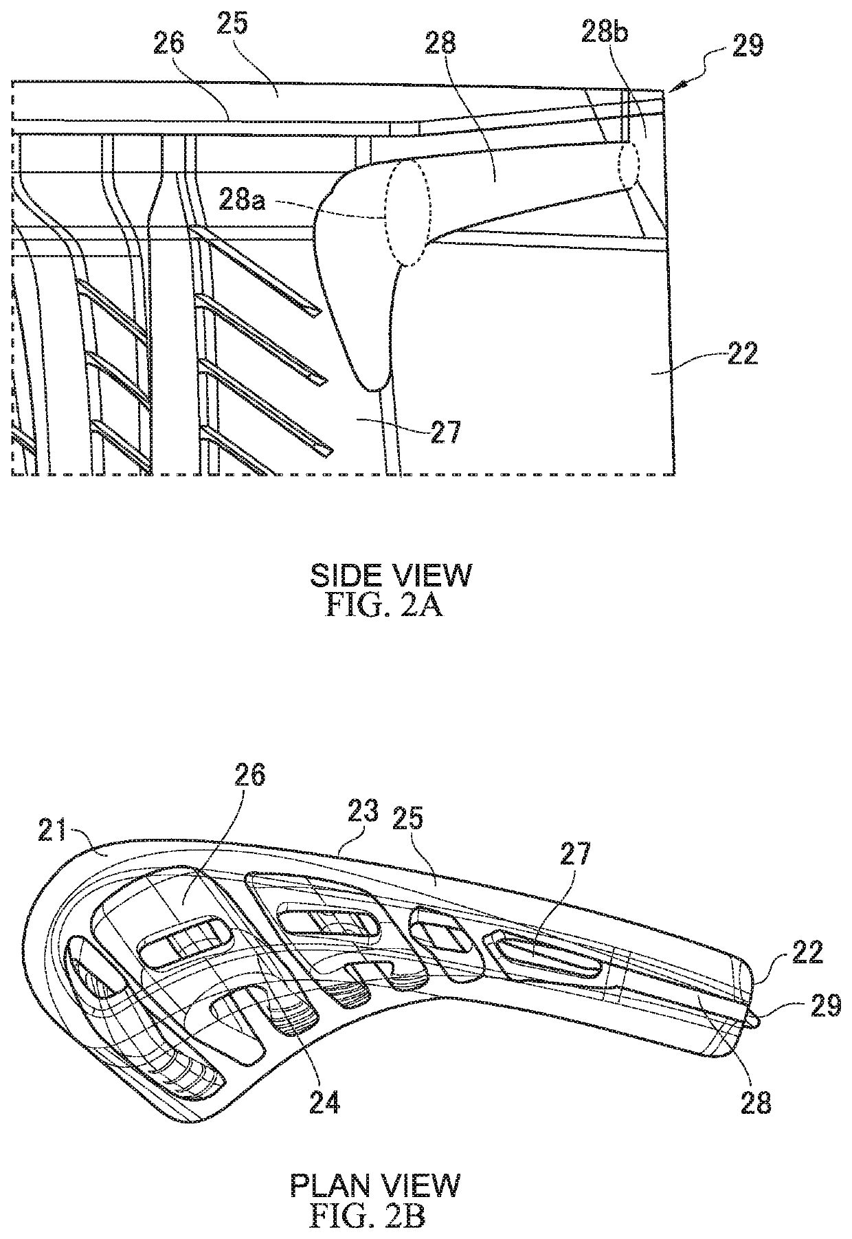
[0031]FIG. 2 shows side and plan views of a blade tip configured in accordance with the invention. As can be seen, the tip includes a leading edge 21, a trailing edge 22, a suction side 23, a pressure side 24, and a squealer wall 25 extending around the perimeter of the tip. The squealer wall 25 bounds a gutter 26. Extending through the elongated portion of the blade in a root to tip direction is a main trailing edge cooling channel 27. The main trailing edge cooling channel 27 exits into the gutter 26. The main trailing edge cooling channel 27 is integrally cast into the blade, its shape being defined by a core positioned in a mould during casting of the blade. The core is subsequently leached out of the cast blade leaving the internal channel 27. As compared to the prior art, the core for manufacturing the illustrated embodiment is extended to include a gallery channel section which defines the gallery channel 28. The gallery channel has an open end 28a intersecting the main trail...


PUM


Abstract

A blade has a root portion and elongate portion extending from the root portion to a tip. The elongate portion has an aerofoil-shaped cross section having leading and trailing edges and suction and pressure sides. The tip may include a gutter defining squealer. The squealer has a wall extending from the trailing edge and along a substantial portion of the tip perimeter. A main trailing edge cooling channel extends within the elongate portion in a direction from root to tip adjacent the trailing edge and exiting into the gutter. A gallery channel is arranged just behind the gutter and extends from an open end intersecting the main trailing edge cooling channel to a closed end located just behind a trailing edge apogee. Cooling channels extend from the gallery channel and through the squealer wall. The gallery channel diameter is greater at the open end than the closed end.

Description

FIELD OF INVENTION[0001]The present invention relates to shroudless turbine blades. More particularly the invention relates to the arrangement of internal cooling channels in the tip region of such blades and the geometry of the blades at their tip.BACKGROUND TO INVENTION[0002]In a gas turbine engine, a compressor is arranged to compress air for delivery to a combustor. The combustor mixes the compressed air with fuel and ignites the mixture. Gas products of this combustion are directed at a turbine blade assembly causing rotation of the blades and the production of power from the turbine assembly. Combustion temperatures may exceed 1400° C. and typical configurations expose the turbine blade assemblies to these high temperatures. Turbine blades are made of materials capable of withstanding such high temperatures and often contain cooling systems for prolonging the life of the blades, reducing the likelihood of failure as a result of exposure to these excessive temperatures.[0003]A ...

Claims


Application Information

Patent Timeline
Patent Type & Authority Patents(United States)
IPC IPC(8): F01D5/18F01D5/20F01D5/14
CPCF01D5/187F01D5/20F01D5/147F05D2240/304F05D2260/202F05D2240/306F05D2240/305F05D2220/32
Inventor MOTTRAM, MARTINSELLERS, PAUL A
Owner ROLLS ROYCE PLC
Why Eureka
Try Eureka