
Power source load control

Active Publication Date: 2020-11-17
COOPER J CARL
View PDF71 Cites 27 Cited by
  • Summary
  • Abstract
  • Description
  • Claims
  • Application Information

AI Technical Summary

Benefits of technology

The present invention is about controlling the load that a power source can handle to keep it at or near its maximum capacity. It also aims to optimize power source efficiency by connecting and operating loads at the best time, while avoiding overload and saving power during times of low cost. The invention allows for efficient matching of loads to power sources and prevents overloading of power sources by controlling the connection and disconnection of loads and controlling power drawn from power sources. Overall, the invention improves reliability and efficiency of power sources and allows for flexible and efficient use of power.

Problems solved by technology

As used herein and in the claims, overload means a load that if not disconnected or otherwise prevented will either cause a departure from specifications for the power output from the power source, for example such as a deviation of AC power voltage or frequency for longer than a specified time period, a loss of power such as from a tripped circuit breaker, or damage such as overheating or exceeding mechanical stress limits.
When making decisions which are aimed at efficiency, one substantial consideration is the cost of providing power.

Method used


Image

  • Power source load control
  • Power source load control
  • Power source load control

Examples


Embodiment Construction

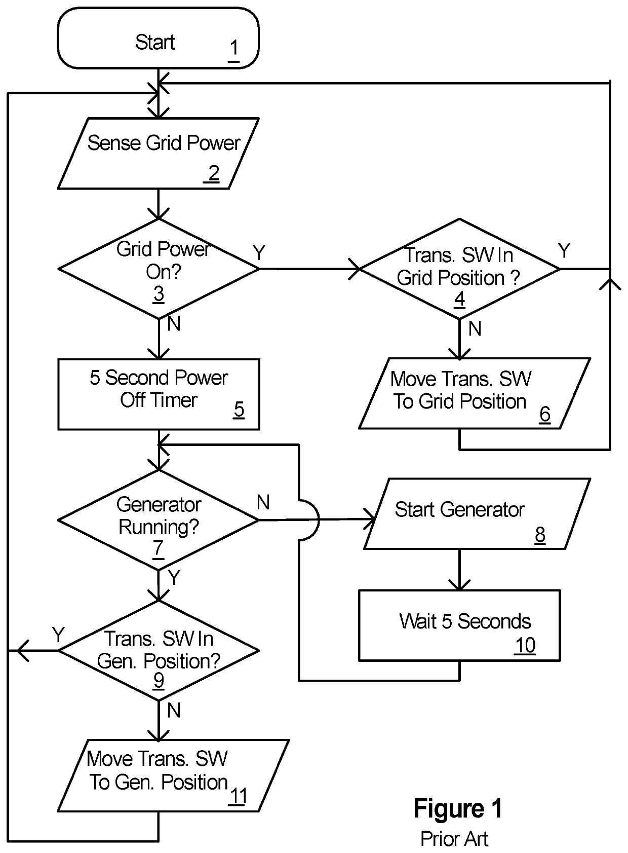
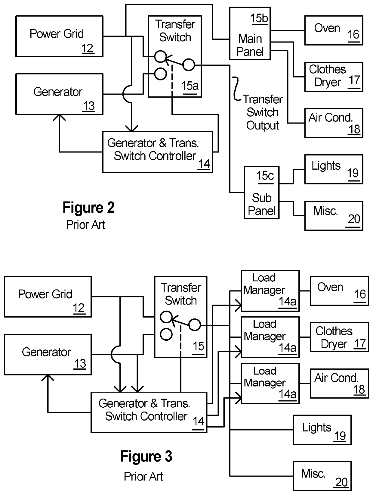
[0060]FIGS. 1-3 provide background for understanding of prior art electrical power backup power systems as they pertain to the present invention. One of ordinary skill will already know these systems and the FIGS. 1-3 are simplified to aid in understanding some of the shortcomings of the prior art which are overcome by the present invention. As just one example, it will be known that the connections shown in the various FIGS. 1-3 (and 4-21D) often represent a plurality of actual circuits, such as the connection from the utility power grid 12 which may entail several conductors ranging from three for a single phase system to six or even more for multiple phase systems.

[0061]FIG. 2 shows a prior art power backup system to power some of the loads 16-20 utilizing a service connection to a power grid 12 as the primary power source and a generator 13 as the backup power source. As is well known in the art, the figures herein, including FIG. 2, are drawn in single line form, that is, a sin...


PUM


Abstract

A method and apparatus for managing one or more grid supplied and separately metered power services, backup power sources, transfer switches and related powered loads using load monitoring and control which allow selectively connecting, disconnecting, limiting and controlling various loads which are powered thereby. The method and apparatus include operating with a system with a dual revenue meters providing grid power, a backup power source and a dual transfer switch wherein the power capabilities of each are economically sized while allowing reliability and convenience in selecting and powering loads. The connections to power sources and control of the loads powered thereby take into account various parameters including cost of power, load handling capability, type of load, load size, environmental factors, load usage during and subsequent to load connection, load priority and operator wishes.

Description

[0001]This application is a continuation in part of, and incorporates herein by reference in its entirety application Ser. No. 13 / 481,804 filed May 26, 2012 titled Power Source Load Control which application in turn claims benefit of, and incorporates by reference herein in their entirety, provisional patent applications: Power Source Load Control, application No. 61 / 490,253 filed May 26, 2011; Power Source Load Control, application No. 61 / 552,722 filed Oct. 28, 2011; Load Control, application No. 61 / 598,564 filed Feb. 14, 2012 and Genset Overload Control, application No. 61 / 624,360 filed Apr. 15, 2012.BACKGROUND OF THE INVENTION[0002]The background of the invention, summary of the invention, brief description of the Figures, detailed description of the preferred embodiment, claims and abstract are presented and described herein to a person having ordinary skill in the art to which the subject matter pertains, hereinafter sometimes referred to as person of ordinary skill or one of o...

Claims


Application Information

Patent Timeline
IPC IPC(8): H02J9/06H02J3/14
CPCH02J3/14H02J9/06Y02B70/3225H02J2310/14Y04S20/248Y04S20/242H02J3/0075H02J3/32H02J7/35H02J13/00004Y04S20/222Y02B70/30Y02B90/20Y04S20/12
Inventor COOPER, J. CARL
Owner COOPER J CARL
Learn More