Preventing sub-harmonic oscillation with clock delay compensation, in a DC-DC switching converter

a switching converter and clock delay technology, applied in the direction of electric variable regulation, pulse manipulation, instruments, etc., can solve the problems of sub-harmonic oscillation, negative effects on the wider system, and inability to operate under certain operating conditions

Active Publication Date: 2020-11-17
DIALOG SEMICON UK
View PDF48 Cites 1 Cited by
  • Summary
  • Abstract
  • Description
  • Claims
  • Application Information

AI Technical Summary

Benefits of technology

[0004]Accordingly, it is an object of one or more embodiments of the present disclosure to provide a method to prevent sub-harmonic oscillation in a switching regulator, configured for peak-current-mode or valley-mode control, allowing the switching regulator to remain fully stable.
[0006]The above and other objects are further achieved by a method for preventing sub-harmonic oscillation in a current-mode switching regulator. A high-side switch and a low-side switch are provided. A system clock synchronizes the switching regulator. A clock delay generation circuit, with a clock signal from the system clock as an input, is provided. A delayed-clock signal for turning on the high-side switch or the low-side switch is generated.

Problems solved by technology

The difference between the average inductor current and the dc value of the sampled inductor current can cause instability for certain operating conditions.
This instability is known as sub-harmonic oscillation, which occurs when the inductor ripple current does not return to its initial value by the start of the next switching cycle.
In some systems, this compensation ramp can have negative effects on the wider system, and the control loop no longer behaves like a current converter.

Method used


Image

  • Preventing sub-harmonic oscillation with clock delay compensation, in a DC-DC switching converter
  • Preventing sub-harmonic oscillation with clock delay compensation, in a DC-DC switching converter
  • Preventing sub-harmonic oscillation with clock delay compensation, in a DC-DC switching converter

Examples


Embodiment Construction

[0032]Compensation ramps remove sub-harmonic oscillation in peak-current-mode and valley-mode control switching converters, when the control loop is controlling the peak-current. When the buck converter hits the current limit, included to prevent damage to the buck or any loads supplied by the buck, the peak-current is fixed and the compensation ramp ceases to have any effect. At this point the buck will suffer sub-harmonic oscillation. The disclosure provides a method of preventing sub-harmonic oscillation, which allows the switching converter to remain fully stable, even when in current limit, increasing the maximum current.

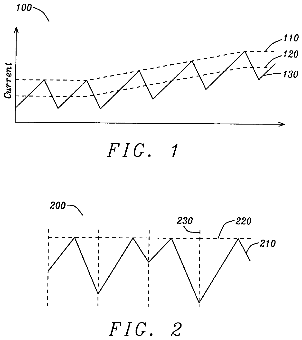
[0033]FIG. 1 shows the coil current of a buck converter, compared to the peak-current and defined range of the open loop gain, of the prior art. In buck converter 100, the high-side output switch of the buck converter is turned on by a clock signal. Once the switch is on, current 130 in the coil increases linearly. Once the current in the coil reaches a thresho...


PUM


Abstract

The clock input of a buck converter is delayed, and the delay is controlled proportionally to the preceding high-side output switch on time. In the steady state, the high-side switch on time is uniform, and the clock is offset by a fixed amount. When sub-harmonic oscillation begins to occur, the high-side switch on time may increase during a cycle. The longer high-side on time causes the clock to be delayed by an increased amount. This has the effect of increasing the following low-side output switch on time. This further increases the subsequent high-side on time, and counteracts the effects of sub-harmonic oscillation. If the system is properly controlled, loop compensation is implemented correctly and sub-harmonic oscillation is prevented. In addition, the scheme may also be configured for the delay to be controlled proportionally to the preceding low-side output switch on time of the buck converter.

Description

BACKGROUND OF THE INVENTIONField of the Invention[0001]The present disclosure relates generally to Buck, Boost, and other types of switching converters, and more specifically to peak-current-mode, valley-mode control, and sub-harmonic oscillation in a switching converter.Description of Related Art[0002]The difference between the average inductor current and the dc value of the sampled inductor current can cause instability for certain operating conditions. This instability is known as sub-harmonic oscillation, which occurs when the inductor ripple current does not return to its initial value by the start of the next switching cycle. Sub-harmonic oscillation is normally characterized by observing alternating wide and narrow pulses at the switching node. A peak-current-mode switching converter requires a compensation signal to be subtracted at higher duty-cycles to prevent sub-harmonic oscillation, and that a valley-mode control switching converter requires a compensation signal to be...

Claims


Application Information

Patent Timeline
Patent Type & Authority Patents(United States)
IPC IPC(8): H02M3/158H02M3/155H03K5/135H02M1/14
CPCH02M3/158H02M3/155H03K5/135H02M1/14
Inventor CHILDS, MARKMASUCH, JENS
Owner DIALOG SEMICON UK
Why Eureka
Try Eureka