Vane assembly, turbine including vane assembly, and gasturbine including vane assembly

a technology of gas turbine and assembly, which is applied in the direction of stators, machines/engines, mechanical equipment, etc., can solve the problems of reducing the operational movement range and high speed operability, and achieve the effects of preventing the leakage of compressed air, and preventing the concentration of thermal stress

Active Publication Date: 2020-11-24
DOOSAN HEAVY IND & CONSTR CO LTD
View PDF74 Cites 1 Cited by
  • Summary
  • Abstract
  • Description
  • Claims
  • Application Information

AI Technical Summary

Benefits of technology

[0011]The present disclosure has been made in view of the above problems occurring in the related art, and an objective of the present disclosure is to provide a vane assembly being capable of preventing thermal stress being concentrated on a hook portion of a shroud of a turbine vane fixed to a turbine casing, a turbine comprising the vane assembly, and a gas turbine comprising the turbine.
[0012]According to one aspect of the present disclosure, there is provided a turbine configured to generate driving force to be used for generation of electric power by allowing a combustion gas supplied from a combustor to pass therethrough, the turbine comprising: a turbine section comprising a plurality of turbine rotor disks and a plurality of turbine blade airfoils coupled to an outer surface of each of the plurality of turbine rotor disks; a turbine casing accommodating the turbine section; and a plurality of vane assemblies provided inside the turbine casing and arranged between the turbine blade airfoils, wherein each of the turbine vane assemblies comprises a vane airfoil configured to guide a flow direction of the combustion gas, a platform portion combined with an end of the vane airfoil, carrier hook portions provided at respective periphery portions of the platform portion and arranged to face the turbine casing so as to be fixed to the turbine casing, and a seal plate installed in a thermal stress prevention slot provided to the carrier hook portion facing the turbine casing, thereby preventing a portion of compressed air supplied to the platform portion between the carrier hook portions by a compressor from leaking to an outside of the platform portion through the thermal stress prevention slot.
[0013]According to another aspect of the present disclosure, there is provided a gas turbine comprising: a compressor taking in air and compressing the intake air; a combustor burning fuel by using compressed air supplied from the compressor to produce combustion gas; and a turbine comprising a turbine section having a plurality of turbine rotor disks rotated by the combustion gas supplied from the combustor and a plurality of turbine blade airfoils coupled to an outer surface of each of the plurality of turbine rotor disks, a turbine casing accommodating the turbine section, and a plurality of vane assemblies provided inside the turbine casing and arranged between the turbine blade airfoils, wherein each of the turbine vane assemblies comprises a vane airfoil configured to guide a flow direction of the combustion gas, a platform portion combined with an end of the vane airfoil, carrier hook portions provided at respective periphery portions of the platform portion and arranged to face the turbine casing so as to be fixed to the turbine casing, and a seal plate installed in a thermal stress prevention slot provided to the carrier hook portion facing the turbine casing, thereby preventing a portion of the compressed air supplied to the platform portion between the carrier hook portions by the compressor from leaking to an outside of the platform portion through the thermal stress prevention slot.
[0014]The vane assembly, the turbine, and the gas turbine according to the present disclosure are configured such that thermal stress prevention slots are provided in carrier hook portions provided at both periphery portions of a platform portion of the vane assembly, so that the carrier hook portions are hooked by a vane carrier of the turbine casing, thereby preventing concentration of thermal stress.
[0015]The seal plates are inserted into the thermal stress prevention slots, thereby preventing the compressed air from leaking through the thermal stress prevention slots. Thus, stable cooling of the turbine vane assembly can be achieved.

Problems solved by technology

Therefore, it has no mutual frictional part such as a piston-cylinder part, thereby consuming an extremely small amount of lubricating oil and reducing the operational movement range, thus resulting in high speed operability.

Method used


Image

  • Vane assembly, turbine including vane assembly, and gasturbine including vane assembly
  • Vane assembly, turbine including vane assembly, and gasturbine including vane assembly
  • Vane assembly, turbine including vane assembly, and gasturbine including vane assembly

Examples


Embodiment Construction

[0021]Hereinafter, a turbine according to one embodiment of the present disclosure will be described with reference to the accompanying drawings.

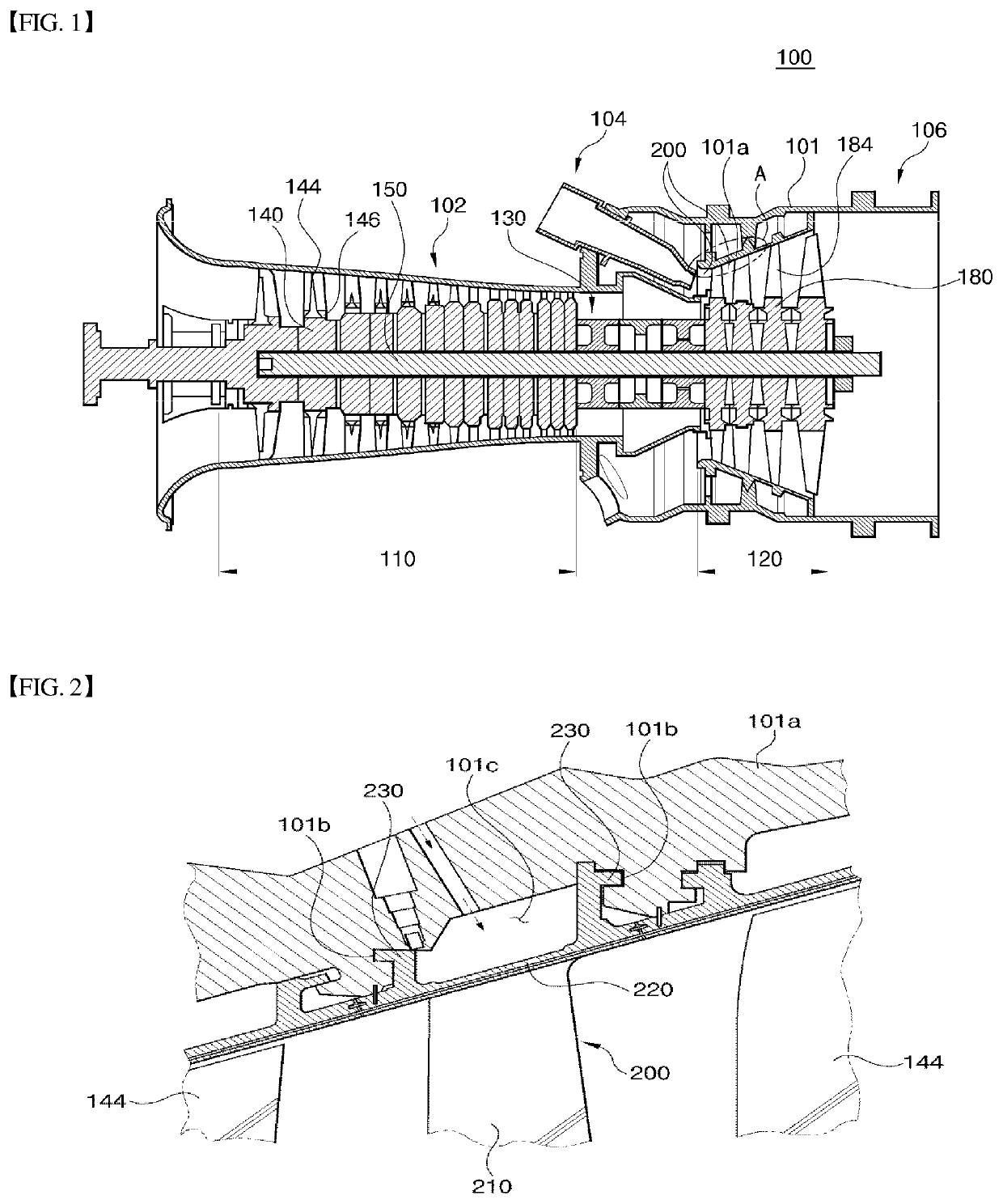
[0022]FIG. 1 illustrates a gas turbine 100 according to one embodiment of the present disclosure. The gas turbine 100 comprises a compressor casing 102 and a diffuser 106 disposed at the rear side of the compressor casing 102 and through which combustion gas having passed through the turbine is discharged to outside. A combustor 104 is arranged in front of the diffuser 106. The combustor 104 receives compressed air from the compressor section 110 of the compressor and performs combustion with the compressed air.

[0023]In terms of the direction of air flow, the compressor section 110 is disposed at the upstream side of the compressor casing 102, and a turbine section 120 is disposed at the downstream side of the compressor casing 102. A torque tube 130 for transmitting torque generated by the turbine section 120 to the compressor section 110 ...


PUM


Abstract

Disclosed is a vane assembly fixed to a turbine casing of a turbine and configured to guide the flow of combustion gas having passed by a turbine blade airfoil. The vane assembly comprises a vane airfoil configured to guide the flow of the combustion gas, a platform portion combined with an end of the vane airfoil, carrier hook portions formed at respective periphery portions of the platform portion and provided with a thermal stress prevention slot on a surface facing the turbine casing, and a seal plate installed in the thermal stress prevention slot, thereby preventing a portion of compressed air produced by a compressor and supplied to the platform portion between the carrier hook portions from leaking out of the platform portion through the thermal stress prevention slot.

Description

CROSS REFERENCE TO RELATED APPLICATION[0001]This application claims the benefit of Korean Patent Application No. 10-2017-0116498, filed on Sep. 12, 2017, in the Korean Intellectual Property Office, the disclosure of which is incorporated herein in its entirety by reference.BACKGROUND OF THE DISCLOSURE1. Field of the Disclosure[0002]The present disclosure relates to a vane assembly that guides the flow of high-temperature, high-pressure combustion gas through airfoils of multistage turbine blades as well as a turbine including the vane assembly and a gas turbine including the vane assembly.2. Description of the Related Art[0003]A turbine is a rotary mechanical device that rotates by an impulse or a reaction force to a flow of compressible fluid, such as gas. Turbines are categorized into steam turbines using steam as the compressible fluid and gas turbines using hot combustion gas as the compressible fluid.[0004]A gas turbine is mainly composed of a compressor section, a combustor se...

Claims


Application Information

Patent Timeline
Patent Type & Authority Patents(United States)
IPC IPC(8): F01D25/24F01D9/04F01D5/14F02C7/28
CPCF01D9/042F01D25/246F01D9/04F02C7/28F01D5/14F05D2220/32F05D2270/112F05D2240/55F01D25/24F05D2240/12F01D11/001F02C7/20F05D2240/14
Inventor SONG, JIN WOO
Owner DOOSAN HEAVY IND & CONSTR CO LTD
Why Eureka
Try Eureka