Quick release purge valve and substrate container using same

a technology of purge valve and substrate container, which is applied in the direction of valve housing, separation process, instruments, etc., can solve the problems of deteriorating image quality projected onto the wafer, inefficient component replacement process, etc., and achieves the effect of facilitating component replacement, saving work time, and increasing work efficiency

Active Publication Date: 2020-12-29
GUDENG PRECISION IND CO LTD
View PDF23 Cites 4 Cited by
  • Summary
  • Abstract
  • Description
  • Claims
  • Application Information

AI Technical Summary

Benefits of technology

[0006]In view of the above-mentioned problems, the present invention is to provide a quick release purge valve and a substrate container using the same, which use a detachable snap plate to increase the convenience of replacing the components.
[0017]According to the disclosure of the embodiments of the invention, the quick release purge valve and the substrate container using the same use the detachable snap plate to fix the gasket fitting. When the snap plate and the bottom plate are in the disengaged state, the gasket fitting is removable from the base, which facilitates component replacement by the user, and thus the work time can be saved and the work efficiency can be increased. Further, the snap plate is at most evenly aligned with the bottom plate to keep the bottom of the substrate container a flat surface, which is advantageous to the transportation of the substrate container and beneficial for keeping the cleanliness as well.

Problems solved by technology

During the photolithography process, any particle attached on the reticle would deteriorate the image quality projected onto the wafer.
The work of screwing, removing, and reinstalling is quite time consuming, making the component replacement process very inefficient.

Method used


Image

  • Quick release purge valve and substrate container using same
  • Quick release purge valve and substrate container using same
  • Quick release purge valve and substrate container using same

Examples


Embodiment Construction

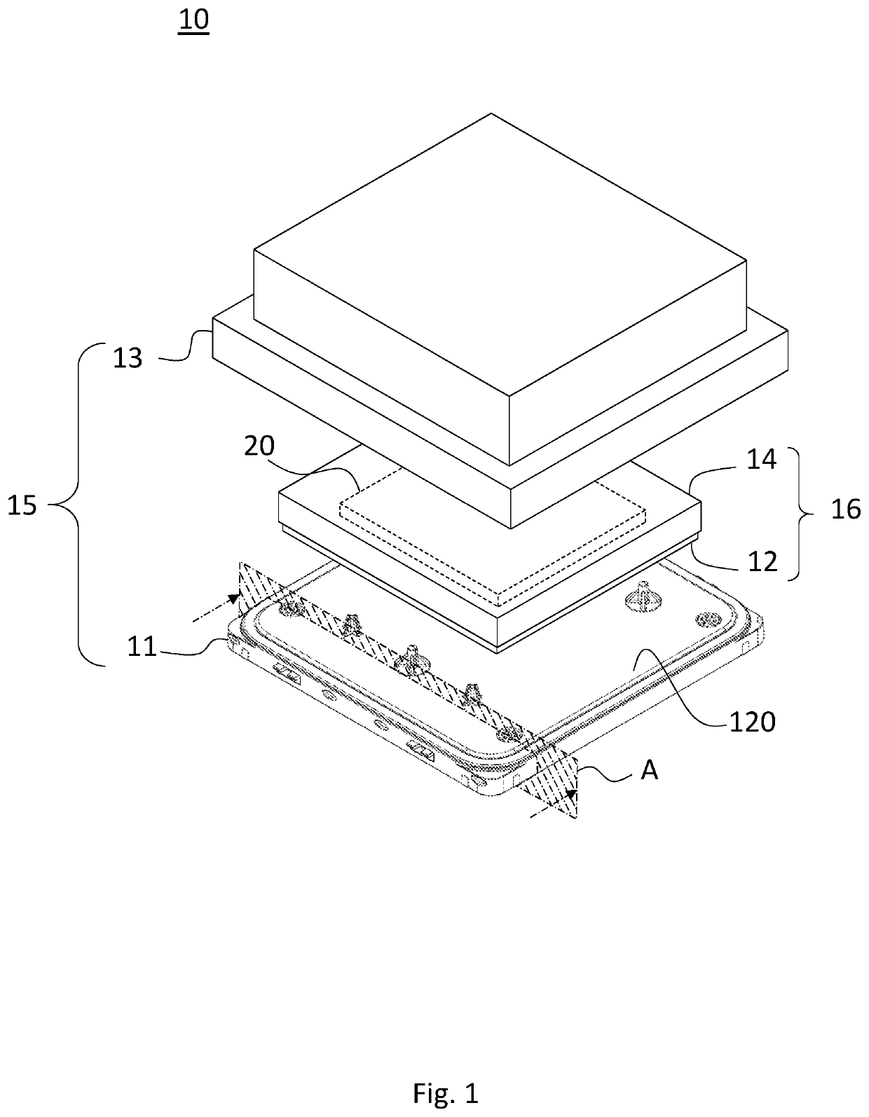
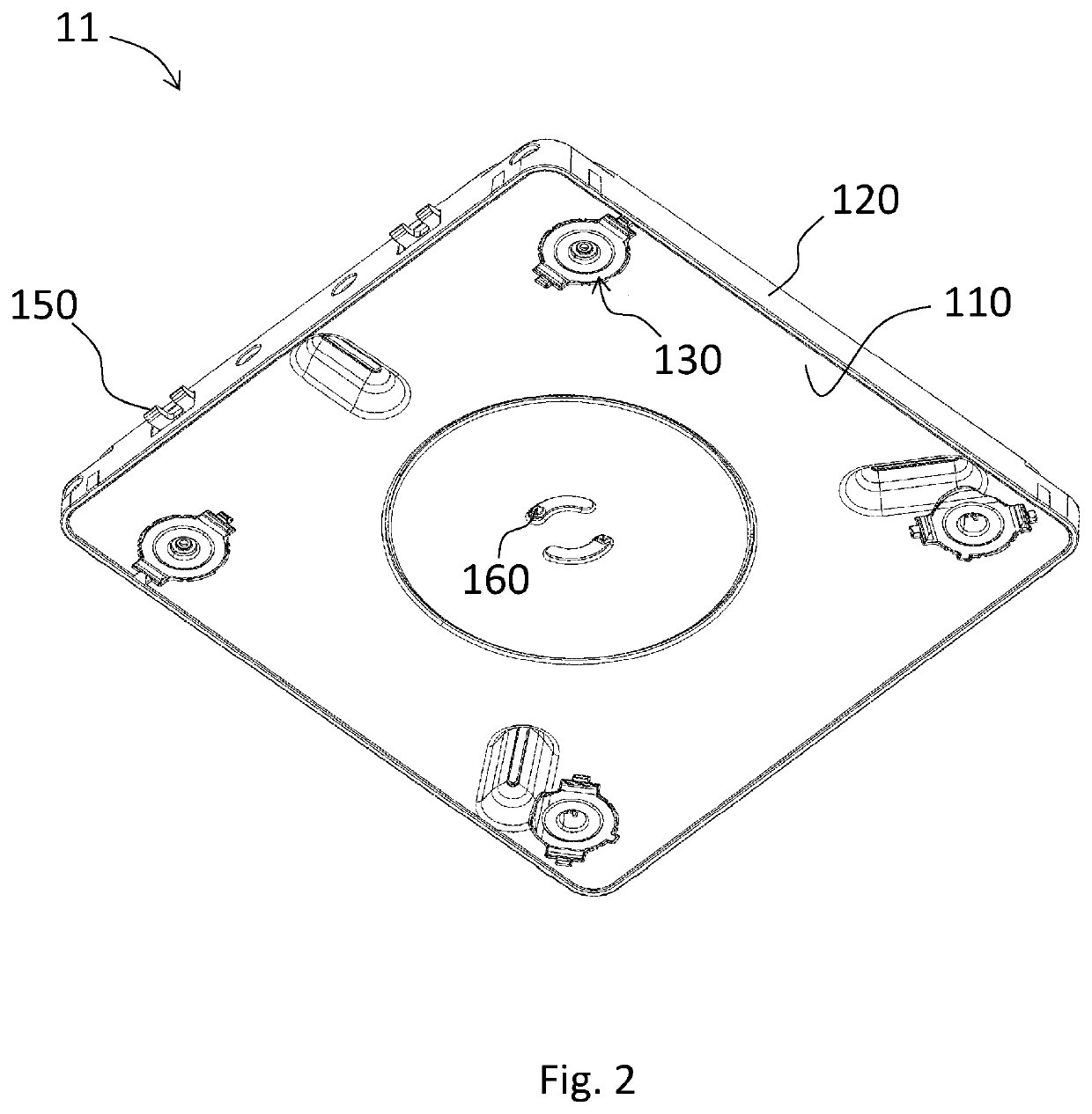
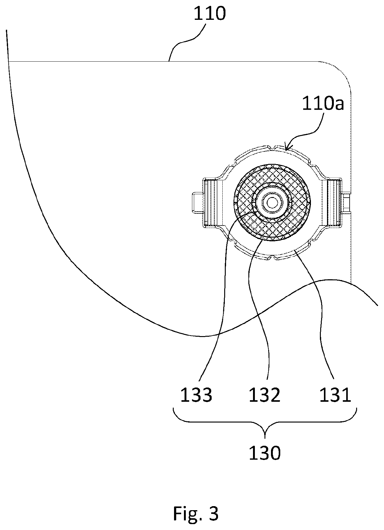
[0026]In the embodiments of the quick release purge valve and the substrate container using the same according to the embodiments of the invention, the quick release purge valve allows the gas entering or leaving the substrate container. The substrate container includes a base having a cover plate and a bottom plate. The quick release purge valve includes a snap plate, a gasket fitting, and a valve element. The snap plate is detachably engaged to a first opening of the bottom plate and is at most evenly aligned with the bottom plate. The gasket fitting is disposed between the cover plate and the bottom plate and has an airflow conduit communicating the cover plate and the bottom plate. The valve element is disposed in the airflow conduit for limiting the flow direction of the gas.

[0027]The gasket fitting is configured to be fixed in the base when the snap plate and the bottom plate are in an engaged state, so that the gasket fitting can be prevented from moving out of the base. The ...


PUM

PropertyMeasurementUnit
outer diameteraaaaaaaaaa
inner diameteraaaaaaaaaa
light permeableaaaaaaaaaa

Abstract

A quick release purge valve and a substrate container using the same are provided. The substrate container has a base including a bottom plate, a cover plate, and a quick release purge valve. The quick release purge valve includes a snap plate, a gasket fitting, and a valve element. The snap plate detachably engages with the bottom plate and is at most evenly aligned with the bottom plate. The gasket fitting is disposed between the cover plate and the bottom plate and has an airflow conduit communicating the two plates. The valve element is disposed in the conduit for limiting a flow direction of the gas. The gasket fitting is fixed in the base when the snap plate and the bottom plate are in an engaged state and is removable from the base when the snap plate and the bottom plate are in a disengaged state.

Description

RELATED APPLICATIONS[0001]This application claims priority to U.S. Provisional Patent Application, No. 62 / 615,986, by Chiu, et al., titled “Quick Replacement Mechanism for Purge Filter,” filed Jan. 11, 2018 which is hereby incorporated by reference herein in their entirety.BACKGROUND OF THE INVENTIONTechnical Field[0002]The present invention relates to a quick release purge valve. More particularly, the present invention relates a quick release purge valve applied in a substrate container.Description of Related Art[0003]Along with the development of technology, the technologies related to semiconductor manufacturing advance rapidly. Among the manufacturing processes, the photolithography process plays a key role. Photolithography involves patterning the light permeable reticle with predefined pattern, projecting the pattern on the reticle onto a wafer by exposing to a light source. As a result, the pattern can be transferred and developed on the wafer. During the photolithography pr...

Claims


Application Information

Patent Timeline
Patent Type & Authority Patents(United States)
IPC IPC(8): F16K24/04H01L21/677F16K27/02B01D46/10B01D46/42
CPCF16K24/04F16K27/0209H01L21/67793B01D46/4272B01D46/10G03F1/66
Inventor CHIU, MING-CHIENCHUANG, CHIA-HOHSUEH, HSIN-MIN
Owner GUDENG PRECISION IND CO LTD
Why Eureka
Try Eureka