Method of measuring sedation using ocular microtremor (OMT) and microsaccades (MS)

a technology of ocular microtrauma and sedation, which is applied in the field of eye sensors, can solve the problems of prolonging the duration, affecting the neural ability of the patient, brain death, etc., and achieves the effects of increasing the sensitivity of the patient, facilitating proper transduction, and maximizing stress and strain and sensitivity

Active Publication Date: 2021-01-12
BRAINSTEM BIOMETRICS INC
View PDF12 Cites 1 Cited by
  • Summary
  • Abstract
  • Description
  • Claims
  • Application Information

AI Technical Summary

Benefits of technology

[0014]It has been found that contemporaneously measuring two or more types of fixational eye movements (e.g. MS and OMT) can provide better insight into the state of the patient. By monitoring these two or more types of fixational eye movement, unique patterns can be found and compared to predetermined values and suggest, and / or automatically take, an action in response to the condition. The use of two or more fixational eye movements enables clinicians to better diagnose a patient's condition in the circumstance where differing underlying conditions present similarly and are previously indistinguishable using conventional instruments single parameter measures and methods available prior to the present invention.
[0015]While the invention is described in terms of MS and OMT movements, it is hypothesized that drift and other fixational movements, when monitored will provide data representative of brainstem activity. What has been discovered is by monitoring at least two fixational eye movements, previously believed by the prior art to be only of independent value, actually better diagnose the state of brainstem than the individual data points.
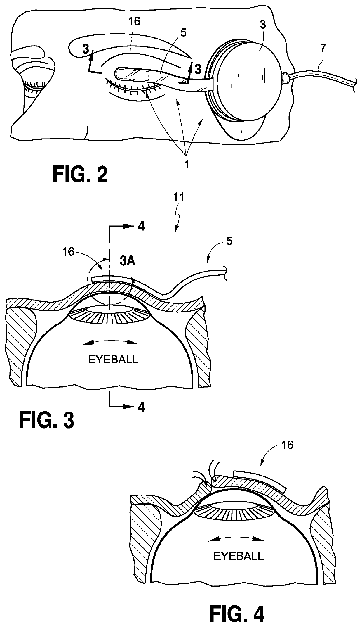
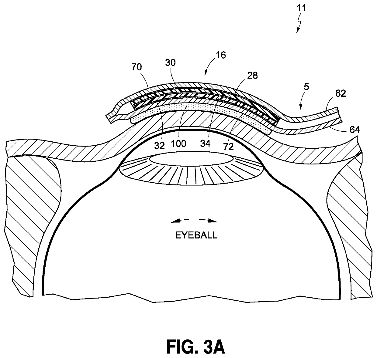
[0024]In some embodiments, the sensor of the eye sensor comprises a piezoelectric element. One embodiment incorporates a single thick piezo layer in the range of 10-60 μm thick which is laminated together with an adjacent structural layer of approximately equal thickness as the piezo layer so as to maximize stress and strain and sensitivity. In some embodiments, piezoelectric element comprises upper and lower thin film forming piezoelectric layers that are joined one above the other in an opposing bimorph fashion by an intermediate bonding agent. In some embodiments, the outside of each of the upper and lower piezoelectric layers has an electrically conductive surface electrodes directly disposed upon the piezo layer to collect the signal created by movement. The sensor of the detector is able to generate the alternating voltage biosignal between the outside conductive surfaces as the upper and lower piezoelectric layers thereof are deflected in response to fixational eye movements of the patient's eyeball. To increase its sensitivity, enable proper transduction reliably without the need for additional measures, enable use during both open and closed eye conditions, and to reduce the discomfort of the wearer, the sensor is attached to the patient's eyelid so as to conform to the shape thereof. Additionally, the sensing element is covered with outer layers of conductive shielding, which are insulated from the conducting electrodes that are disposed of inside.

Problems solved by technology

In some cases, the patient may be over-sedated throughout an operation which could permanently impact his neural ability and possibly cause brainstem death.
In still other cases, over-sedation of a patient may prolong the duration of mechanical ventilation, and under-sedation can result in the patient being subjected to unintended extubation.
For a long time, a primary source of information available to a clinician concerning the depth of anesthesia or sedation was limited to the patient's somatic and autonomic response to physical and / or verbal stimuli.
These responses are known to be susceptible to being altered and influenced by neuromuscular blocking drugs, drugs affecting the autonomic nervous system, and the inconsistency of the stimuli.
Thus, the presence or absence of these responses does not always accurately correlate with conscious awareness and, therefore, can be poor indicators of the depth of the patient's unconscious state.
Therefore the frequency of microsaccades tends to be less reported as useful, and more often the direction, presence or lack of, peak speed or acceleration and amplitude as measures of various phenomenon.
However, the known sensors are relatively large, such that they are limited to being used during surgery when the eyes of the individual being tested are fully closed and taped shut.
Because small micro eye movements have an amplitude of about 500 nanometers, sensor these motions are susceptible to being masked or altered by external electrical and electromagnetic interference as well as physical forces and biological artifacts.
It has been found that attaching some conventional ocular microtremor sensor to a patient's eyelid may result in a focused pressure being applied to the eyelid which creates a depression in the patient's eyeball.
The sometimes intrusive nature of the conventional sensor applying a concentrated pressure to the patient's eyeball can, over time, cause patient discomfort.

Method used


Image

  • Method of measuring sedation using ocular microtremor (OMT) and microsaccades (MS)
  • Method of measuring sedation using ocular microtremor (OMT) and microsaccades (MS)
  • Method of measuring sedation using ocular microtremor (OMT) and microsaccades (MS)

Examples


Embodiment Construction

[0080]It will be appreciated that for simplicity and clarity of illustration, where appropriate, reference numerals and / or names have been repeated among the different figures to indicate corresponding or analogous elements. In addition, numerous specific details are set forth in order to provide a thorough understanding of the embodiments described herein. However, it will be understood by those of ordinary skill in the art that the embodiments described herein can be practiced without these specific details. In other instances, methods, procedures and components have not been described in detail so as not to obscure the related relevant feature being described. The drawings are not necessarily to scale and the proportions of certain parts may be exaggerated to better illustrate details and features. The description is not to be considered as limiting the scope of the embodiments described herein. It should be noted that references to “an” or “one” embodiment in this disclosure are...


PUM


Abstract

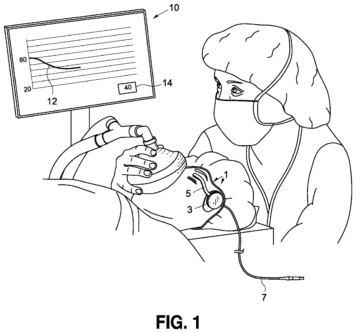
An eye sensor, system and method for measuring fixational eye movements of an individual's eyeball (e.g., ocular microtremors and microsaccades) to provide a variable voltage biosignal for measuring the individual's brainstem activity is provided. The eye sensor comprises a sensor mounted on the individual's closed or opened eyelid so as to be deflected by the fixational eye movements of the eyeball. A shielded flexible ribbon assembly supplies the biosignal generated by the sensor to an amplifier located on the individual's skin where the biosignal is amplified. The amplifier is interconnected with a signal processor and a display by which graphical and numerical representations of the biosignal are made accessible to an anesthesiologist, intensivist or clinician. A method for analyzing the biosignal to determine the brainstem activity of a patient is also provided.

Description

BACKGROUND OF THE INVENTIONField of the Invention[0001]This invention relates to an eye sensor, system and method which displays graphical and numerical representations of one or more of the fixation eye movements of a patient's eyeball (e.g., the cornea / sclera) to provide a monitor (e.g., an anesthesiologist, intensivist or clinician) with an indication of the patient's brainstem activity or altered brainstem state including his level of sedation, consciousness, and responsiveness. This can be used prior to, during and after a medical or clinical procedure, such as, for example, when the patient is anesthetized during an operation. A sensor of the eye sensor is thin and compliant and capable of conforming to the shape of the patient's closed eyelid or being located in the tissue folds of the patient's open eyelid at which to be responsive to the fixational eye movements of the patient's eyeball.Background Art[0002]During the performance and treatment of many medical procedures and ...

Claims


Application Information

Patent Timeline
Patent Type & Authority Patents(United States)
IPC IPC(8): A61B5/00A61B3/00A61B3/113A61B5/16A61B5/18
CPCA61B5/4821A61B3/0025A61B3/0041A61B3/113A61B5/002A61B5/163A61B5/6833A61B5/18A61B5/7203A61B5/7257A61B2562/0247A61B2562/043
Inventor BALTAY, MICHAELRASMUSSEN, BRUCESHEHABI, YAHYABOLGER, CIARANACQUADRO, MARTINFOSTER, CLARK B.
Owner BRAINSTEM BIOMETRICS INC
Why Eureka
Try Eureka