Mixed-domain circuit with differential domain-converters

a technology of differential domain and converter, applied in the field of mixed domain integrated circuit, can solve the problems of low phase noise, explosive growth of data bandwidth requirements, and substantial increase of modern wireline and wireless communication systems

Active Publication Date: 2021-01-19
SI WARE SYST S AE
View PDF7 Cites 36 Cited by
  • Summary
  • Abstract
  • Description
  • Claims
  • Application Information

AI Technical Summary

Problems solved by technology

With the advent of the age of big data and the wide adaption of the internet of things, data bandwidth requirements have seen an explosive growth.
This substantially increased the complexity of modern wireline and wireless communication systems, where

Method used


Image

  • Mixed-domain circuit with differential domain-converters
  • Mixed-domain circuit with differential domain-converters
  • Mixed-domain circuit with differential domain-converters

Examples


Embodiment Construction

[0024]The present invention relates to an improvement in mixed-domain circuits. The following description is presented to enable one of ordinary skill in the art to make and use the invention as provided in the context of a particular application and its requirements. Various modifications to the preferred embodiment will be apparent to those with skill in the art, and the general principles defined herein may be applied to other embodiments. Therefore, the present invention is not intended to be limited to the particular embodiments shown and described but is to be accorded the widest scope consistent with the principles and novel features herein disclosed.

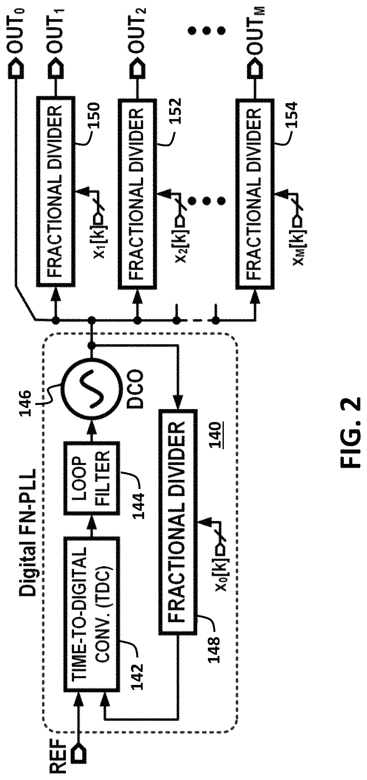
[0025]FIG. 2 shows a block diagram of a clock generation unit using digital FN-PLL and multiple open loop fractional dividers (FDIVs). FN-PLL 140 has TDC 142 that receives feedback from fractional divider 148 to control loop filter 144 that control DCO 146 to generate OUT0.

[0026]FN-PLL 140 generates ultra-low-jitter high frequenc...


PUM


Abstract

A mixed-domain circuit has a differential pair of Digital-to-Time Converters (DTCs), one receiving a reference clock and the other receiving a feedback clock. A Time-to-Digital Converter (TDC) compares outputs from the differential pair of DTCs and generates a digital error value that controls a digital loop filter that controls a Digitally-Controlled Oscillator (DCO) that generates an output clock. A Multi-Modulus Divider (MMD) generates the feedback clock. An accumulated modulation from a delta-sigma modulator is compared to the digital error value by a Least-Mean Square (LMS) correlator to adjust supply voltage or current sources in the pair of DTCs to compensate for errors. A capacitor in each DTC has a charging time adjusted by the accumulated modulation. The DTC can be reduced to a Time-to-Voltage Converter (TVC) and the analog voltages on the capacitors input to an Analog-to-Digital Converter (ADC) to generate the digital error value.

Description

RELATED APPLICATION[0001]This application claims the benefit of provisional application U.S. Ser. No. 62 / 878,735, filed Jul. 25, 2019, hereby incorporated by reference. This application is also related to “Adaptive Nonlinearity Identification and Compensation Using Orthogonal Functions in a Mixed Signal Circuit”, U.S. Pat. No. 10,594,329, filed Dec. 7, 2018, hereby incorporated by reference.FIELD OF THE INVENTION[0002]This invention relates to mixed-domain Integrated Circuits (ICs) and more particularly to clock generators, frequency synthesizers, and time-based data converters.BACKGROUND OF THE INVENTION[0003]With the advent of the age of big data and the wide adaption of the internet of things, data bandwidth requirements have seen an explosive growth. This substantially increased the complexity of modern wireline and wireless communication systems, where spectrally efficient complex modulation schemes are being employed. It poses stringent performance requirements to achieve the ...

Claims


Application Information

Patent Timeline
IPC IPC(8): H03M3/00G04F10/00H03M1/34H03L7/197H03L7/099H03L7/093
CPCG04F10/005H03M1/34H03M3/358H03M3/368H03L7/093H03L7/0991H03L7/1976H03M1/466H03M1/125H03M1/066H03M1/50H03M7/3004H03L7/0814H03L7/085H03L7/081
Inventor ELKHOLY, AHMED
Owner SI WARE SYST S AE
Why Eureka
Try Eureka