Wireless power transmitter

a wireless power transmitter and wireless technology, applied in electric power, electric vehicles, transportation and packaging, etc., can solve the problems of power receiver b>30/b>a generating heat, adverse effects on the reliability of internal circuit elements of power receivers, etc., and achieve the effect of uniform characteristics and reduced circuit area

Active Publication Date: 2021-01-19
ROHM CO LTD
View PDF7 Cites 2 Cited by
  • Summary
  • Abstract
  • Description
  • Claims
  • Application Information

AI Technical Summary

Benefits of technology

[0010]Examples of the “wireless device” include wireless power transmitters and devices configured to support wireless communication. With this embodiment, such an arrangement is capable of detecting a neighboring wireless device employing the same frequency as that of the transmission frequency of the wireless power transmitter, or a frequency band in the vicinity of the transmission frequency, before the supply of power is started. This arrangement is capable of preventing an excessive supply of power to a power receiver that is receiving a supply of power from another wireless power transmitter, and of preventing electromagnetic wave interference with wireless communication of a communication device.
[0015]With an embodiment, the wireless power transmitter may further include a reception coil. Also, the wireless device detector may detect the wireless device based on an electrical state of the reception coil before electric power transmission is started. In this case, the reception coil can be designed such that it is suitable for detecting a neighboring wireless device, thereby allowing the detection sensitivity to be improved.
[0017]Also, the power transmission control circuit may be configured such that, when the wireless device is detected, electric power is not transmitted. This provides improved safety.
[0023]Examples of such an “integrated” arrangement include: an arrangement in which all the circuit components are formed on a semiconductor substrate; and an arrangement in which principal circuit components are monolithically integrated. Also, a part of the circuit components such as resistors and capacitors may be arranged in the form of components external to such a semiconductor substrate in order to adjust the circuit constants. By integrating the circuit on a single chip, such an arrangement allows the circuit area to be reduced, and allows the circuit elements to have uniform characteristics.

Problems solved by technology

In some cases, this leads to a problem of the power receiver 30A generating heat.
Also, this has the potential to cause adverse effects on the reliability of internal circuit elements of the power receiver 30A.

Method used


Image

  • Wireless power transmitter
  • Wireless power transmitter
  • Wireless power transmitter

Examples


first embodiment

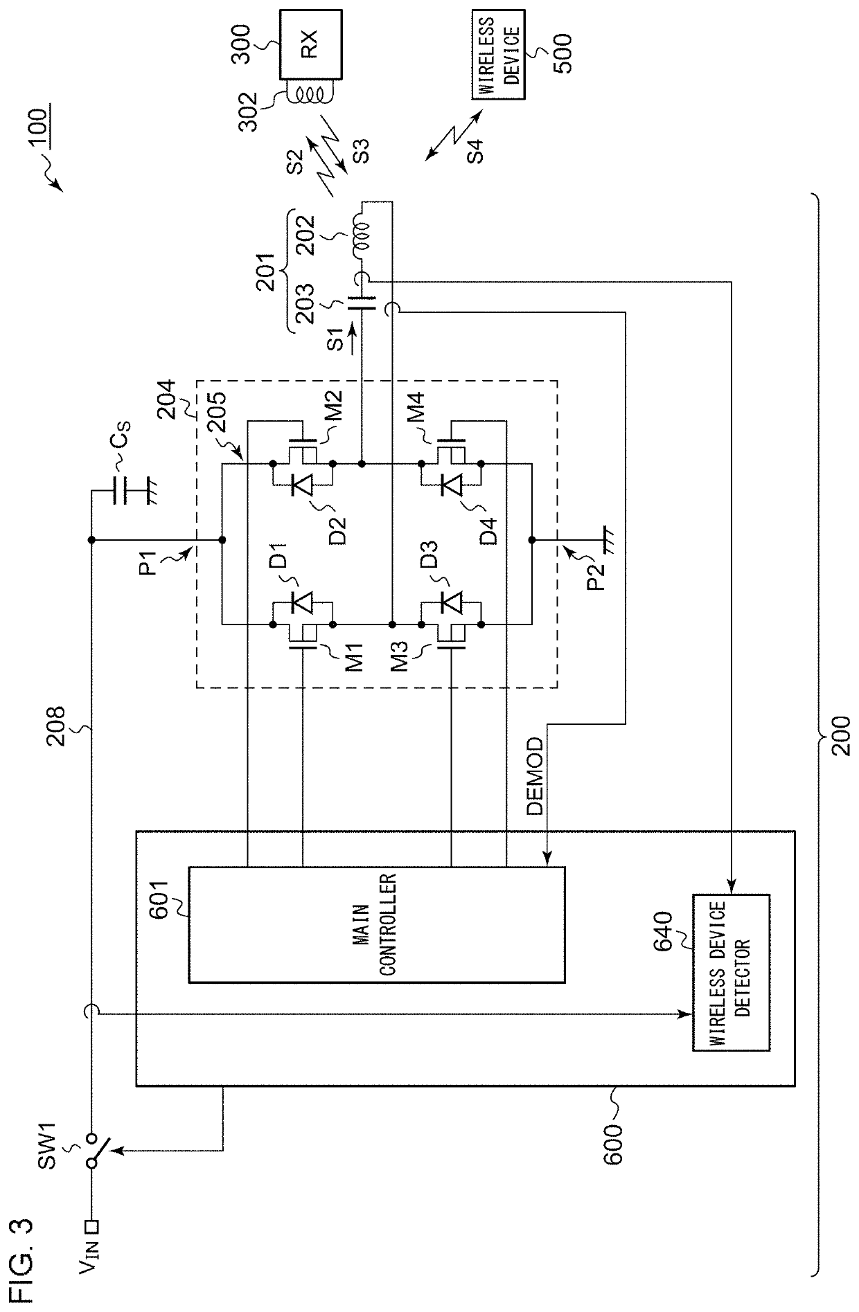
[0035]FIG. 3 is a block diagram showing a power supply system 100 including a wireless power transmitter 200 according to a first embodiment. The power supply system 100 includes a power transmitter 200 and a power receiver 300. The power receiver 300 is mounted on an electronic device such as a cellular phone terminal, smartphone, audio player, game machine, tablet terminal, or the like. The power transmitter 200 conforms to at least one from among the Qi standard and the PMA standard. Description will be made in the present embodiment regarding a configuration and an operation that conform to the Qi standard.

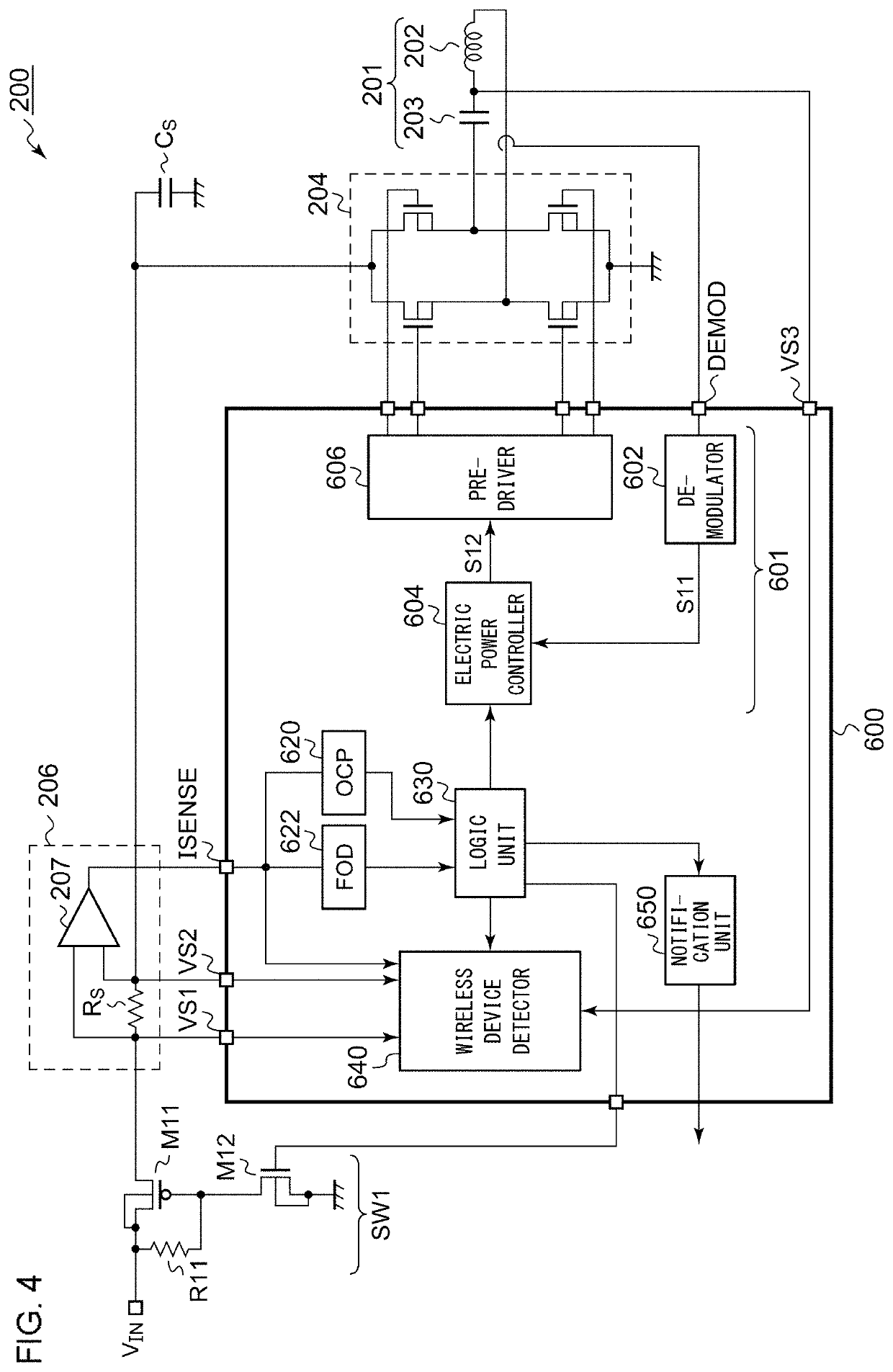
[0036]The power transmitter 200 is mounted on a charger including a charging stand. The power transmitter 200 includes a transmission antenna 201, a driver 204, a high-side switch SW1, and a power transmission control circuit (which will be referred to as a “TX controller” hereafter) 600.

[0037]The transmission antenna 201 includes a transmission coil 202 and a resonance capaci...

second embodiment

[0068]Description has been made in the first embodiment regarding an arrangement using the transmission antenna 201 as a sensor for detecting the wireless device 500. In contrast, a power transmitter according to a second embodiment is provided with a dedicated antenna for detecting the wireless device 500.

[0069]FIG. 5 is a block diagram showing a power supply system 100a including a power transmitter 200a according to the second embodiment. The power transmitter 200a includes a reception antenna 251. The reception antenna 251 includes a reception coil 252 and a resonance capacitor 253 coupled with the reception coil 252 in series (or otherwise in parallel). The resonance frequency and the Q value of the reception antenna 251 may be designed such that they cover the frequency of the electromagnetic wave S4 to be generated by the wireless device 500. The reception antenna 251 may be configured as a replica of the transmission antenna 201.

[0070]The wireless device detector 640 detects...


PUM


Abstract

A power transmitter transmits an electric power signal S2 to a wireless power receiver. A transmission antenna includes a transmission coil and a resonance capacitor coupled in series. A driver applies a driving signal S1 to the transmission coil. A TX controller controls the driver. A wireless device detector of the TX controller detects a neighboring wireless device before electric power transmission is started.

Description

CROSS REFERENCE TO RELATED APPLICATION(S)[0001]This application is a bypass continuation under 35 U.S.C. § 120 of PCT / JP2017 / 001997, filed Jan. 20, 2017, which is incorporated herein reference and which claimed priority to Japanese Application No. 2016-033268, filed Feb. 24, 2016. The present application likewise claims priority under 35 U.S.C. § 119 to Japanese Application No. 2016-033268, filed Feb. 24, 2016, the entire content of which is also incorporated herein by reference.BACKGROUND OF THE INVENTION1. Field of the Invention[0002]The present invention relates to a wireless power transmission, and particularly to an abnormal state detection function of a wireless power transmitter.2. Description of the Related Art[0003]In recent years, as a power supply method for supplying electric power to an electronic device, a wireless power supply method has been becoming popular. Such a wireless power supply method can be classified into two methods, i.e., the magnetic induction (MI) met...

Claims


Application Information

Patent Timeline
Patent Type & Authority Patents(United States)
IPC IPC(8): H02J50/60H02J50/10H02J50/80H02J50/90H02J50/05H02J7/02H02J7/04
CPCH02J50/60H02J7/025H02J7/042H02J50/05H02J50/10H02J50/80H02J50/90
Inventor IWASAKI, TATSUYA
Owner ROHM CO LTD
Why Eureka
Try Eureka