Reaming and self-rotating anchor rod and using method thereof

a self-rotating, anchor rod technology, applied in the direction of mining structures, using optical means, instruments, etc., can solve the problems of inability to keep up with the stopping speed, the coordination between tunneling and stopping is always an important factor, and the impact of coal production, so as to shorten the construction time, simplify the supporting process of coal walls, and reduce the time required for anchor rod installation

Active Publication Date: 2021-02-02
CHINA UNIV OF MINING & TECH
View PDF9 Cites 0 Cited by
  • Summary
  • Abstract
  • Description
  • Claims
  • Application Information

AI Technical Summary

Benefits of technology

[0005]To overcome the drawbacks in the prior art, the present invention provides a reaming and self-rotating anchor rod that can shorten supporting time and avoid an abandoned hole phenomenon incurred by hole collapse, anchor failure, or hole blockage, and is simple to manufacture, low in cost, and simple and convenient to operate; in addition, the present invention further provides a working method using the reaming and self-rotating anchor rod.
[0014]c. starting the anchor rod bolter, driving the reaming and self-rotating anchor rod to advance quickly in the existing small hole to accomplish reaming under the action of the rotation of the drill bit on the front part of the reaming and self-rotating anchor rod and the pushing force applied by a worker, so that friction force is generated between the anchor rod body and the coal seam; decreasing the drilling rate of the anchor rod bolter when the reaming and self-rotating anchor rod has reached to the bottom of the preformed small hole in the coal seam judged from obvious advancing resistance, utilizing the drill bit on the front part of the anchor rod to rotate the rod body into the coal mass, wherein, since the shape knives on the front part of the drill bit are in middle positions, the powder produced during drilling can be discharged away from the head part of the rod body through the spiral grooves on the side surface of the drill bit, the annular protrusion on the rod body blocks the powder flowing out from the hole and thereby the powder fills the clearance between the rod body and the coal mass; shutting down the anchor rod bolter when the exposed length of the anchor rod body is 30˜150 mm, and separating the connecting member from the symmetric wedge at the tail part of the rod body, wherein, since the self-rotation of the anchor rod, there is a force interaction between the connecting member and the rod body, the rod body ought to retreat by some distance together with the connecting member when the connecting member is separated from the rod body, but the strong springs of the baffle pawls on the drill bit eject at this point and the high-strength baffle plates are pushed open and extend out of the groove cavities to block the rod body from further retreating; then, fitting the tray over the tail part of the rod body and mounting the nut on the tail part of the rod body to fix the tray, and using the anchor rod bolter to rotate the nut to accomplish primary pre-tightening of the anchor rod, so that the anchor rod is squeezed and embedded into the coal mass, and thereby the friction force between the anchor rod and the coal mass is increased, the anchor rod is anchored in the full length, and the installation of a complete set of anchor rod is accomplished;
[0015]d. at 1 h˜2 h after the anchor rod works, tightening up the nut with a wrench for secondary pre-tightening, to prevent prestress relaxation of the anchor rod incurred by working of other anchor rods nearby;
[0018]Benefits: with the above-mentioned technical scheme, the present invention has the following advantages when compared with the prior art:
[0019](1) The coal wall supporting process is simplified, and the supporting time required for anchor rod installation is reduced. The anchor rod can penetrate into the coal mass successfully under the action of the rotation of the drill bit on the front part of the reaming and self-rotating anchor rod and the pushing force applied by the worker, and then the anchor rod is pre-tightened up and the working of the anchor rod is accomplished; such a process does not require drilling a long hole with a drilling machine, avoids using any anchoring agent, and shortens the construction time. The anchor rod is difficult to work owing to the limitation of the cross section of the roadway; a small hole is drilled out with a drilling machine in advance, the reaming and self-rotating anchor rod is placed into the small hole and driven to rotate into the coal mass, so that anchoring force for the anchor rod is formed by means of friction force and embedding force generated from squeezing between the anchor rod body and the coal mass, to maintain the stability of the surrounding rocks of the roadway and avoid the problem of hole collapse and blockage incurred by drilling a long hole; thus, the supporting time is greatly reduced, and the requirement for quick tunneling of coal roadways is met. (2) The anchor rod is simple to manufacture, low in cost, simple and convenient to operate, and can be widely applied and has high applicability.

Problems solved by technology

Therefore, coordination between tunneling and stopping is always an important issue in coal production in China.
In recent years, especially since fully mechanized mining automation and information technology is developed, the advancing rate of coal mining working face has been increased continuously, but the tunneling rate hasn't kept up with the stopping speed.
Consequently, the contradiction between tunneling and stopping becomes prominent, the working face replacement becomes tense, causing impact on the coal production.
For modern coal mines, the coal cutting link during tunneling is no longer a major factor that restrains the advancing rate; rather, anchor rod supporting, especially wall supporting, severely restrains the advancing rate.
Presently, a resin anchoring technique is mainly used for wall supporting, but this technique cannot meet the requirement for coal roadway quick tunneling anymore in some cases, owing to the following reasons: the working procedure is complex and time-consuming; the anchoring effect is poor, or even anchoring failure may occur, owing to broken or wet coal mass; the success ratio of long hole drilling in coal walls is very low, and collapse or blockage of the hole occurs often.

Method used


Image

  • Reaming and self-rotating anchor rod and using method thereof
  • Reaming and self-rotating anchor rod and using method thereof
  • Reaming and self-rotating anchor rod and using method thereof

Examples


Embodiment Construction

[0026]Hereunder, an embodiment of the present invention will be further detailed with reference to the accompanying drawings.

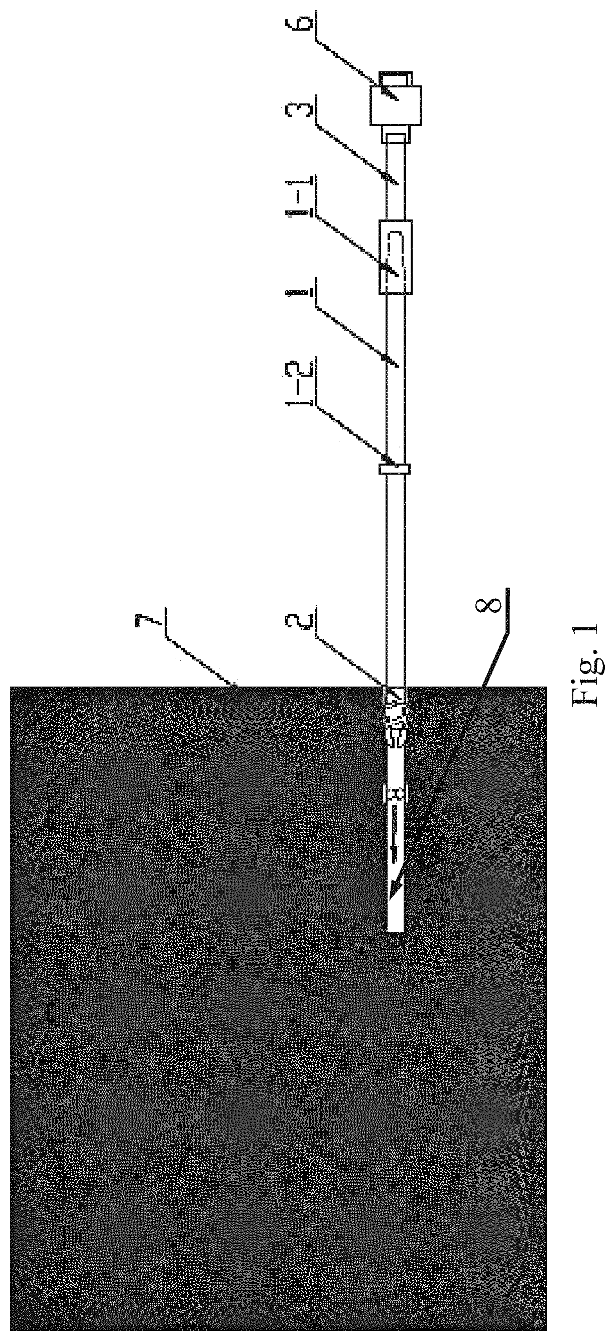
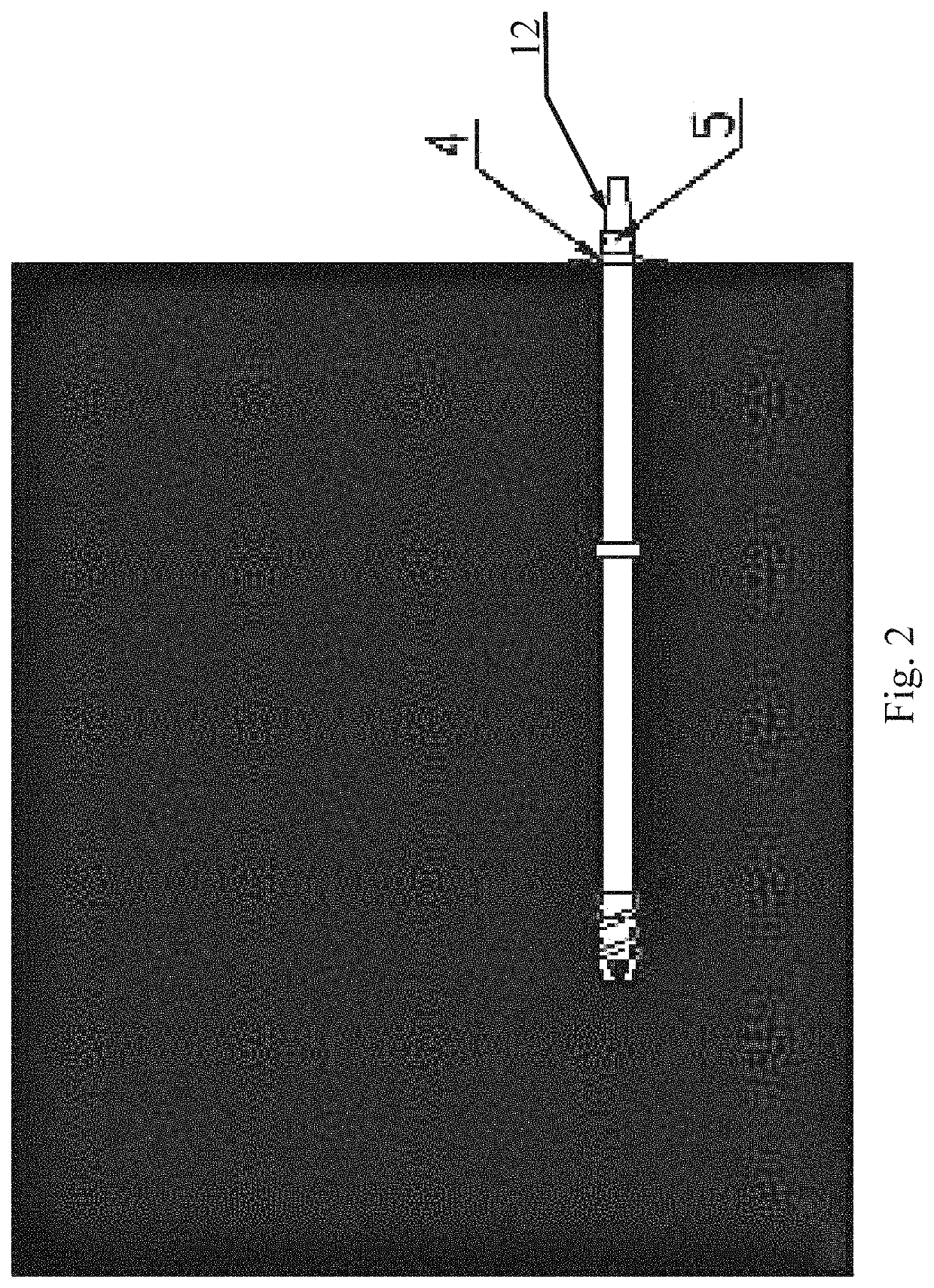
[0027]As shown in FIGS. 1 and 2, the reaming and self-rotating anchor rod provided in the present invention comprises a rod body 1, a drill bit 2, a connecting member 3, and a tightening device, wherein, the rod body 1 has threads without longitudinal rib on the external surface, the drill bit 2 is arranged at the head part of the rod body 1, the head part of the rod body 1 is connected with the drill bit 2 via threads, and the pitch of the drill bit 2 is identical to that of threads without longitudinal rib.

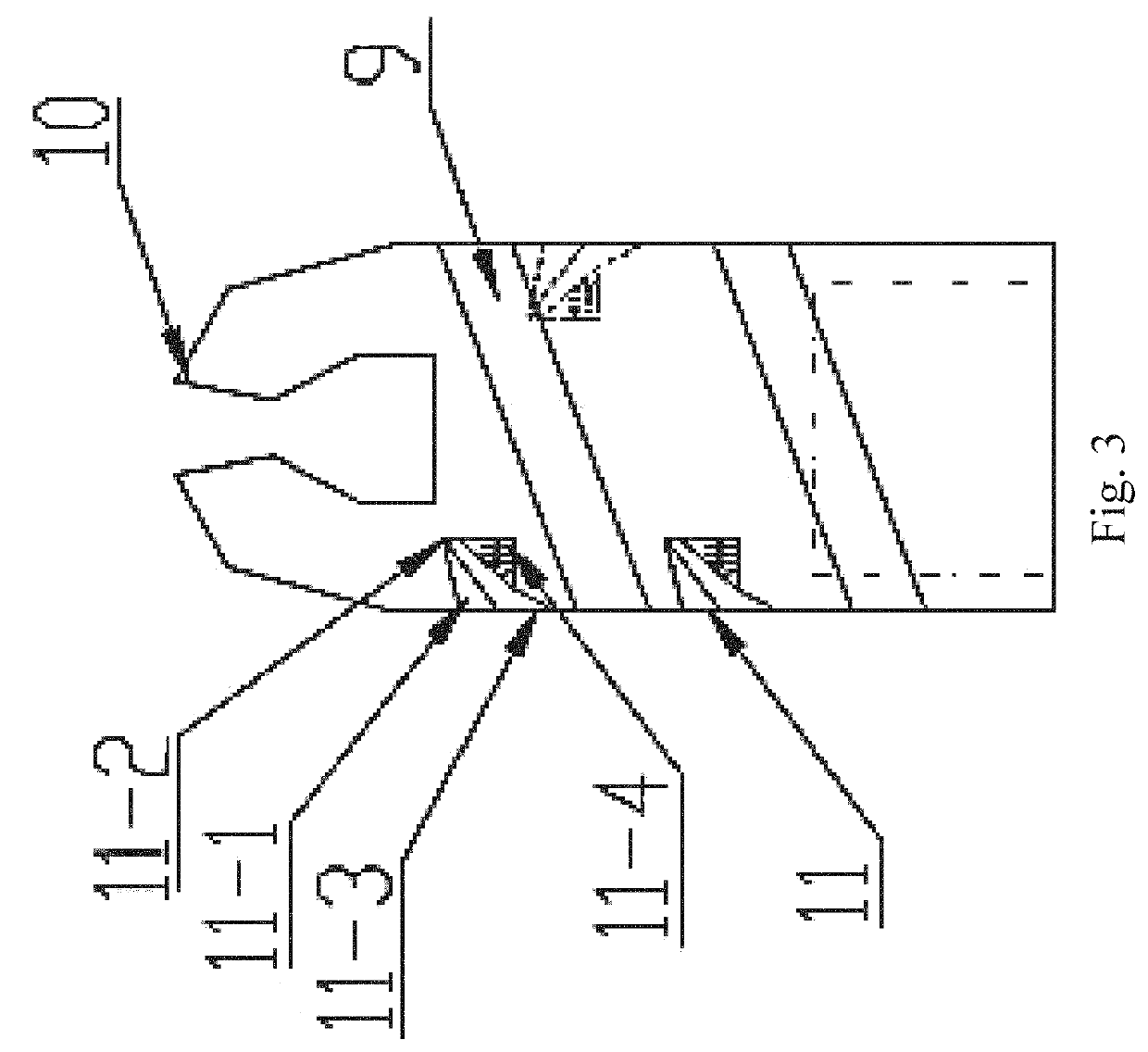
[0028]As shown in FIG. 3, the out diameter of the drill bit 2 is greater than the diameter of the anchor rod body 1 by 3˜8 mm, the drill bit 2 has an opening connected with the anchor rod body 1, a plurality of sharp knives 10 that protrude and incline toward the center of the drill bit 2 are arranged around the opening, the top of each sharp knife 10 is a...


PUM


Abstract

A reaming and self-rotating anchor rod includes a rod body, a drill bit, a connecting member, a tray, and a nut. One end the connecting member is snap-fixed to the tail part of the rod body, the other end of the connecting member is connected to an anchor rod bolter. The rod body has an annular protrusion at its middle part to block powder so that the powder fills up the clearance between the rod body and the coal mass. The drill bit has female threads and can be screwed into the front part of the rod body, and the drill bit has baffle pawls and spiral grooves on its side surface.

Description

CROSS REFERENCE TO RELATED APPLICATIONS[0001]The present application is a 371 U.S. National Stage of International Application No. PCT / CN2017 / 087493, filed Jun. 7, 2017, entitled “REAMING AND SELF-ROTATING ANCHOR ROD AND USING METHOD THEREOF” which in turn claims priority to Chinese Application 201611061660.6 with the same title filed Nov. 25, 2016, both of which are incorporated herein by reference in their entirety.TECHNICAL FIELD[0002]The present invention relates to an anchor rod and a using method thereof, in particular to a reaming and self-rotating anchor rod used for downhole quick tunneling in coal mines and a using method thereof.BACKGROUND OF RELATED ART[0003]In China, the coal mining is mainly underground mining. Tunneling and stopping are important production links for underground coal mining. Therefore, coordination between tunneling and stopping is always an important issue in coal production in China. In recent years, especially since fully mechanized mining automati...

Claims


Application Information

Patent Timeline
Patent Type & Authority Patents(United States)
IPC IPC(8): E21D20/00E21D21/00E21F17/18E21D20/02E21F17/00E21F17/02G01B11/30
CPCE21F17/185E21D20/003E21D20/02E21D21/004E21F17/00E21F17/02G01B11/303G01B11/306E21D20/00E21D21/0026
Inventor ZHANG, NONGXIE, ZHENGZHENGHAN, CHANGLIANG
Owner CHINA UNIV OF MINING & TECH
Why Eureka
Try Eureka