Refractory anchor

a refractory anchor and monolithic technology, applied in the field of anchors, can solve the problems of affecting the uniform application of refractory materials in the vessel wall, and being relatively laborious

Active Publication Date: 2021-02-02
LANCLOS CHRISTOPHER P
View PDF14 Cites 8 Cited by
  • Summary
  • Abstract
  • Description
  • Claims
  • Application Information

AI Technical Summary

Benefits of technology

[0006]In a further aspect, the present invention relates to a solid, monolithic refractory anchor which allows maximum, uniform coverage of the refractory material on the substrate to which the anchor is welded.

Problems solved by technology

Further, the anchor of the 789 Patent is fabricated and is relatively labor intensive to make requiring jigs and fixtures to carry out the various fabrication techniques required to form the anchor sections.
In addition, the fabricated anchor of the 789 Patent has three feet forming weldable appendages which engage, and are welded to, the metal of the vessel or the like, but which make uniform application of the refractory material in the vessel wall more difficult.

Method used


Image

  • Refractory anchor
  • Refractory anchor
  • Refractory anchor

Examples


Embodiment Construction

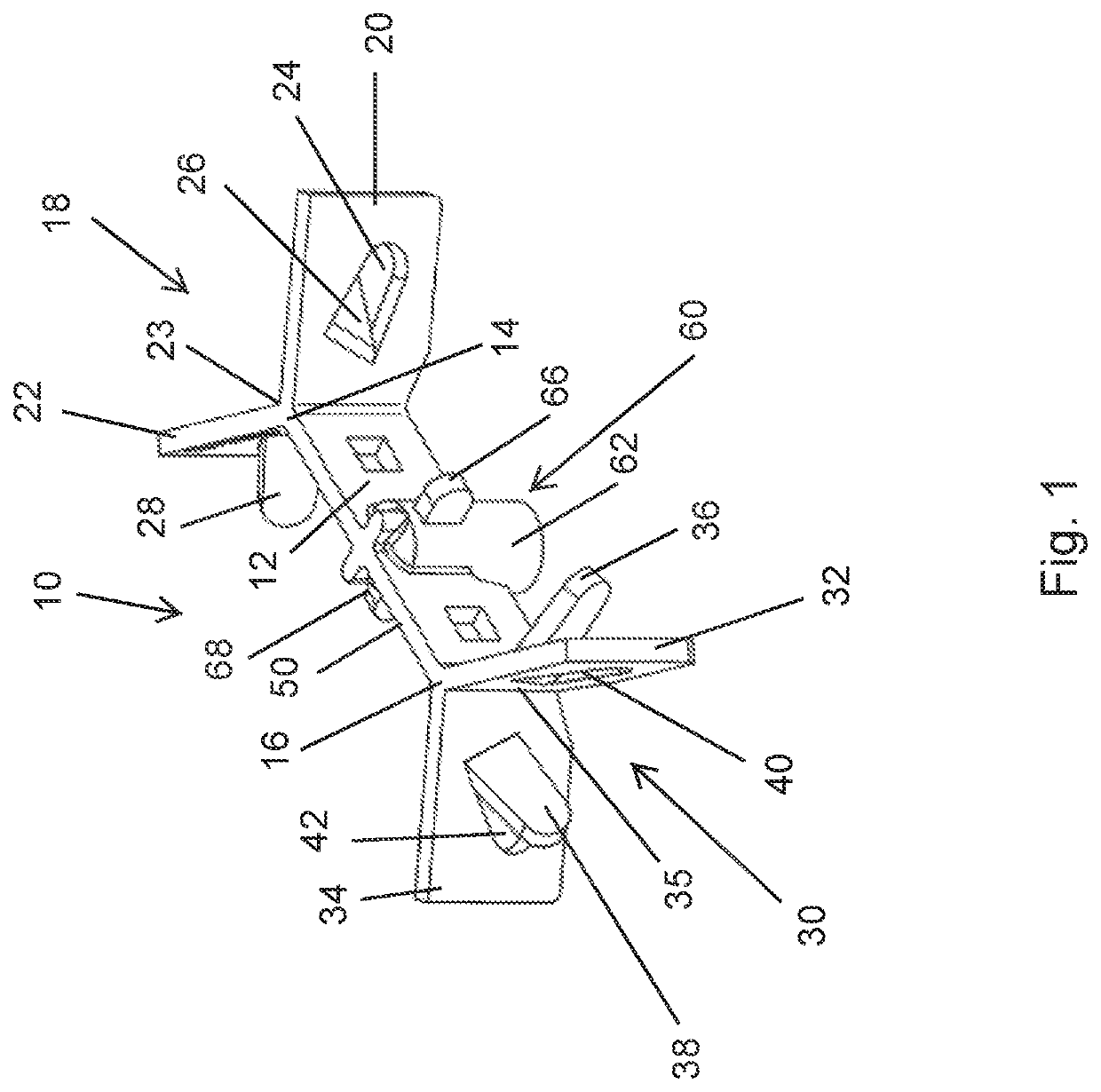
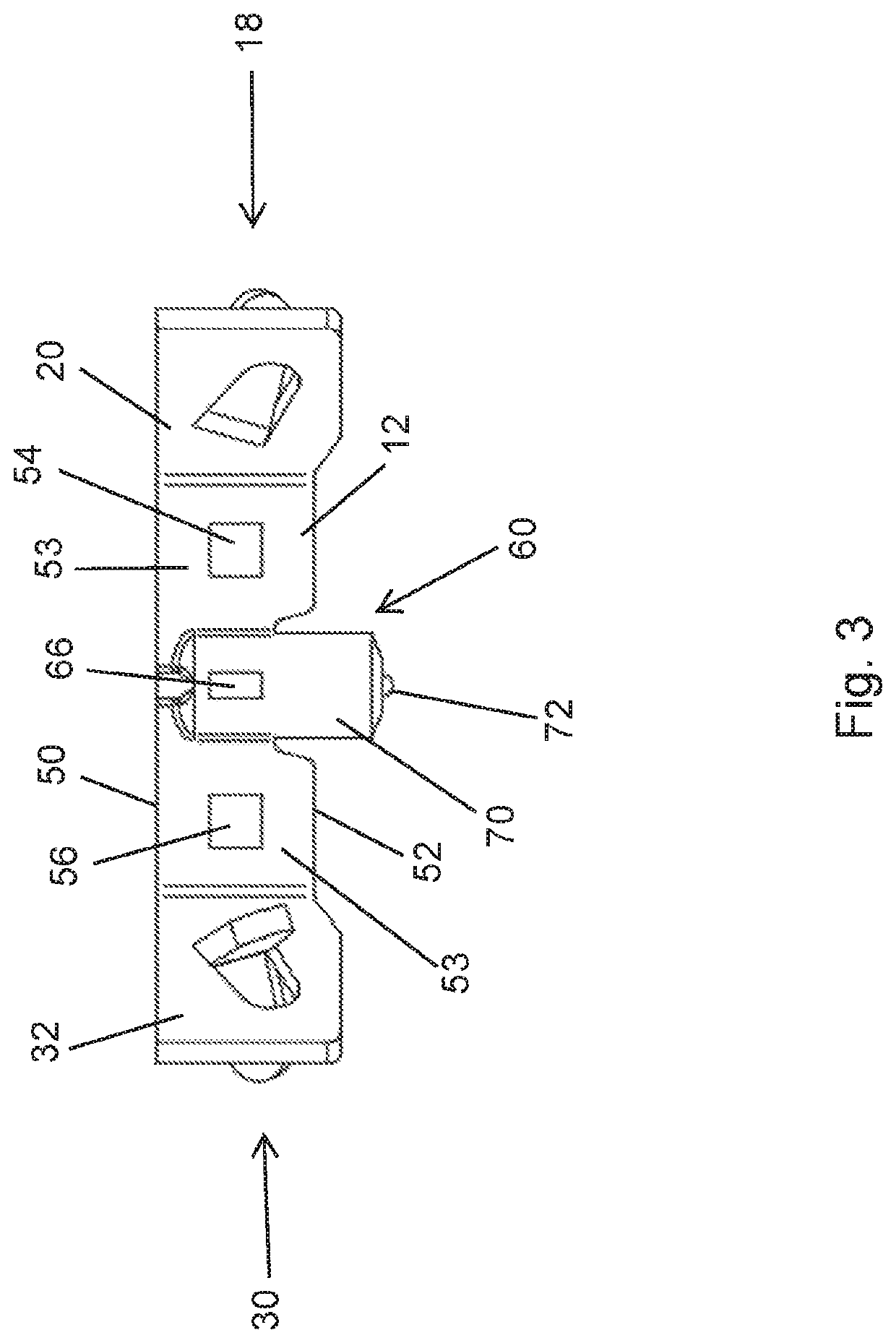
[0016]The terms “upwardly,”“downwardly,”“top,”“bottom,” and similar terms of orientation as used herein are with reference to the anchor as it is depicted in FIG. 3. Thus, “top” or “upwardly” refers to the direction towards the top of the page on FIG. 3 and “bottom” or “downwardly” refers to the direction towards the bottom of the page on FIG. 3. This orientation is for the purposes of describing the invention and does not require that the anchor, in practice, be facing such a direction. It will be understood by those skilled in the art, that the “bottommost” surfaces of the anchor may be sideways or even facing upwardly when positioned in a vessel.

[0017]The refractory anchor of the present invention is a solid, monolithic structure which can be made by any number of casting techniques used in forming metal parts such as, for example, lost-wax casting (investment casting), plaster mold casting, sand casting, etc. Methods of casting metal parts are well known to those skilled in the ...


PUM

PropertyMeasurementUnit
obtuse anglesaaaaaaaaaa

Abstract

A monolithic refractory anchor which has a bridge portion and first and second V-shaped end portions attached to opposite ends of the bridge portion. The anchor has a pedestal located generally centrally of the anchor which extends below the bottom surfaces of the wing portions of the V-shaped sections, the pedestal forming a single welding attachment point for attachment, preferably by stud welding, to a metal substrate.

Description

FIELD OF THE INVENTION[0001]The present invention relates to anchors for refractory linings in process equipment and, particularly, to monolithic anchors which allow maximum coverage of substrates to which the refractory material is applied.BACKGROUND OF THE INVENTION[0002]Refractory linings have been used for many years in process vessels, reactors, conduits, furnaces and the like, to provide thermal insulation, and in environments such as fluidized catalytic reactors or regenerators or stacks, to provide resistance to abrasion or erosion. Such linings serve not only to thermally insulate a shell or other surface, but also to prolong its service life by shielding it from erosion by abrasion. Common refractories include refractory cement, a concrete cement-aggregate mixture, or a reinforced cement or concrete.[0003]To retain the refractory on the metal surface, various anchoring arrangements have been employed. For example, hexagonal stud grating, and weldable studs have been used. ...

Claims


Application Information

Patent Timeline
Patent Type & Authority Patents(United States)
IPC IPC(8): F27D1/14F27D1/00E04B1/41
CPCF27D1/004E04B1/40F27D1/141E04B1/388
Inventor LANCLOS, CHRISTOPHER P.
Owner LANCLOS CHRISTOPHER P
Why Eureka
Try Eureka