Wireless power transmitting device and method

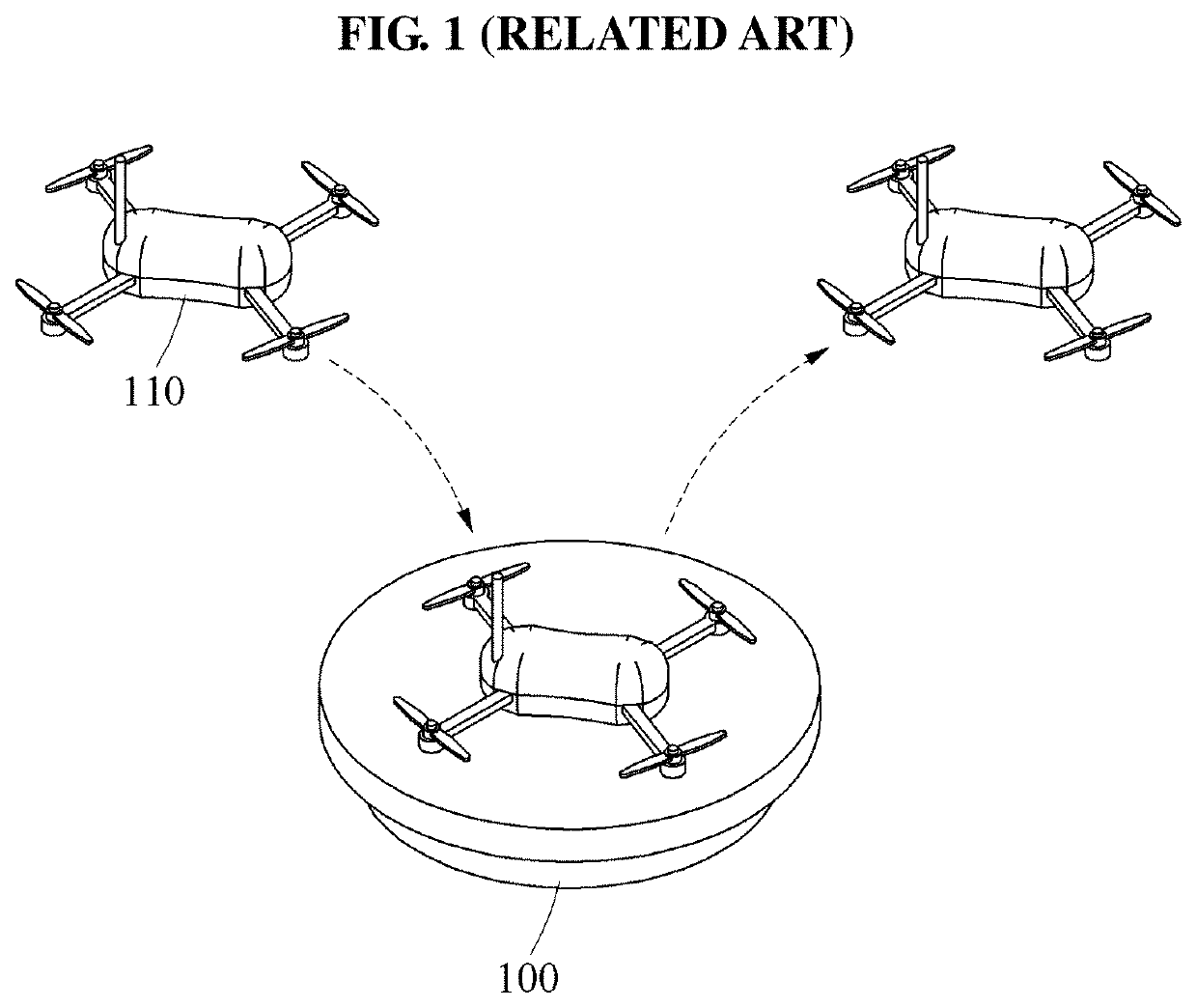
a transmission device and wireless technology, applied in the direction of inductance, transportation and packaging, secondary cell servicing/maintenance, etc., can solve the problems of frequent need for wired charging of batteries, user inconvenience in separating batteries and connecting, and drones may have a relatively short flight time of about 30 minutes, so as to achieve uniform charging efficiency and expand wireless charging coverage

Active Publication Date: 2021-02-02
ELECTRONICS & TELECOMM RES INST
View PDF11 Cites 1 Cited by
  • Summary
  • Abstract
  • Description
  • Claims
  • Application Information

AI Technical Summary

Benefits of technology

[0015]An aspect suggests a new structure of a transmission coil that may expand a wireless charging coverage and maintain a uniform charging efficiency in a wireless power (energy) transmitting device.
[0016]Another aspect also provides a wireless power transmitting device that may enhance a magnetic field that decreases in a central area of a transmission coil in a charging pad by improving a structure of the transmission coil to a multilayer structure in which a plurality of coil layers are stacked in a tapered form, thereby expanding a wireless charging coverage on the charging pad and maintaining a uniform charging efficiency in the entire area of the transmission coil irrespective of a charging position.
[0017]Still another aspect also provides a wireless power (energy) transmitting device that may wirelessly charge a power receiver with a uniform charging efficiency at any position of a reception coil of the power receiver on a transmission coil in a charging pad while expanding a wireless charging coverage by setting an area of the transmission coil to be relatively great when compared to an area of the reception coil.
[0018]Yet another aspect also provides a wireless power transmitting device that may wirelessly charge mobile devices of various sizes and expand a wireless charging coverage by adjusting a diameter of a primary transmission coil being wound to form a first coil layer (the uppermost layer) in a transmission coil with a multilayer structure based on a maximum area of a charging pad.
[0019]Further another aspect also provides a wireless power transmitting device that may enhance an intensity of a magnetic field in a central area of a transmission coil by stacking a secondary coil having a lesser diameter than a primary transmission coil on a second coil layer under the primary transmission coil, and stacking a tertiary transmission coil having a lesser diameter than the secondary coil under the secondary coil.
[0020]Still another aspect also provides a wireless power transmitting device that may have a uniform magnetic field density in the entire area of a transmission coil by enhancing an intensity of a magnetic field in a central area of the transmission coil using a magnetic substance such as ferrite core disposed at a core of the transmission coil.

Problems solved by technology

However, the devices include batteries of limited capacities and thus, wired charging of the batteries are needed frequently.
In particular, a drone may have a relatively short flight time of about 30 minutes.
A user may experience inconvenience in separating a battery and connecting a cable thereto for charging.
Meanwhile, in a case of a mobile device such as a drone, an error may occur in a landing point when the mobile device moves to a charging pad for charging.
In particular, when the reception coil of the power receiver is positioned close to a central portion of the transmission coil of the charging pad, an insufficient rectified voltage may be generated such that the power receiver may not be charged.
Further, when the wireless charging coverage is expanded to dispose multiple transmission coils on a plane in the charging pad, an unnecessary standby current may be consumed to simultaneously supply power to all transmission coils for charging, which may result in a decrease in a charging efficiency.
In this example, to detect a portion of the transmission coils aligned with a reception coil of a power receiver and supply power only to the detected portion, a separate control circuit and a separate algorithm may be needed, which may lead to an increase in the implementation complexity and an increase in the product price.
In this example, an error may occur in a landing point.
However, the charging efficiency and the rated voltage may gradually decrease toward the central area of the transmission coil 200, or charging may be impossible in the central area of the transmission coil 200.
As described above, in a wireless power transmitting device using an existing transmission coil, the distribution of charging efficiency may be non-uniform, and particularly, the charging efficiency may decrease greatly in a central area of the transmission coil.
In a case of supplying power by controlling multiple small transmission coils through a separate control circuit, implementation thereof may be complex.

Method used


Image

  • Wireless power transmitting device and method
  • Wireless power transmitting device and method
  • Wireless power transmitting device and method

Examples


Embodiment Construction

[0042]Hereinafter, some example embodiments will be described in detail with reference to the accompanying drawings. Regarding the reference numerals assigned to the elements in the drawings, it should be noted that the same elements will be designated by the same reference numerals, wherever possible, even though they are shown in different drawings. Also, in the description of embodiments, detailed description of well-known related structures or functions will be omitted when it is deemed that such description will cause ambiguous interpretation of the present disclosure.

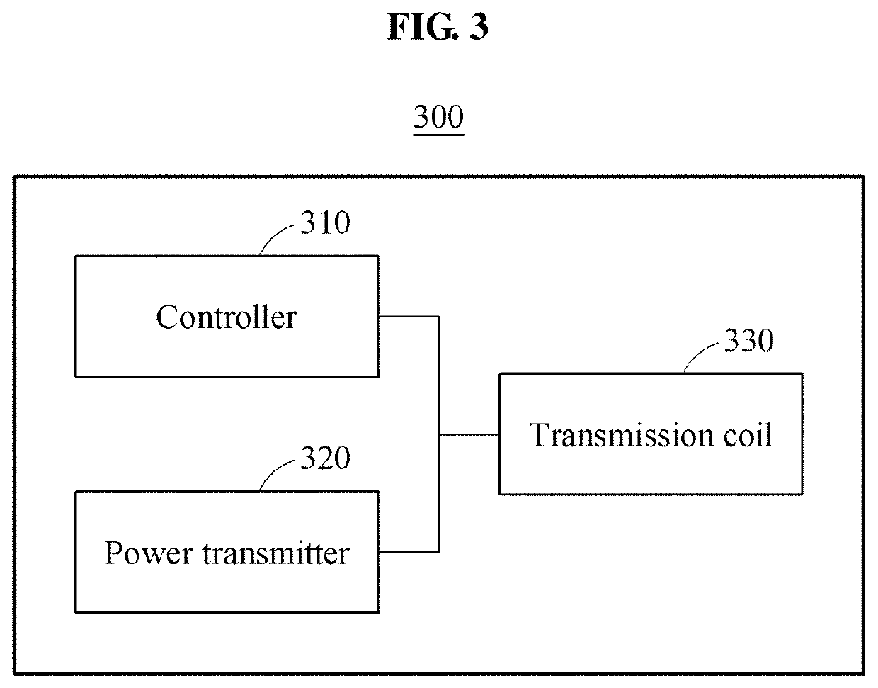
[0043]FIG. 3 is a block diagram illustrating a configuration of a wireless power transmitting device according to an example embodiment.

[0044]Referring to FIG. 3, a wireless power transmitting device 300 may include a controller 310, a power transmitter 320, and a transmission coil 330.

[0045]The controller 310 may generate a magnetic field through the transmission coil 330 with a multilayer structure in a charging...


PUM

PropertyMeasurementUnit
heightaaaaaaaaaa
heightaaaaaaaaaa
widthaaaaaaaaaa

Abstract

Disclosed is a wireless power transmitting device and method, the wireless power transmitting device including, in response to detection of a power receiver within a predetermined separation distance from a charging pad, a controller configured to generate a magnetic field through a transmission coil with a multilayer structure in which a plurality of coil layers of different sizes are stacked, and a power transmitter configured to wirelessly transmit, to a reception coil of the power receiver, a power signal generated using magnetic fields generated by the plurality of coil layers.

Description

CROSS-REFERENCE TO RELATED APPLICATION(S)[0001]This application claims the priority benefit of Korean Patent Application No. 10-2017-0105743 filed on Aug. 21, 2017, in the Korean Intellectual Property Office, the disclosure of which is incorporated herein by reference for all purposes.BACKGROUND1. Field[0002]One or more example embodiments relate to wireless power (energy) transmission technology, and more particularly, to a wireless power transmitting device and method that may maintain a uniform charging efficiency in the entire area while expanding a wireless power coverage by improving a structure of a transmission coil included in a charging pad to generate a magnetic field.2. Description of Related Art[0003]With the recent wide propagation of mobile devices such as drones to general users, the use of multimedia and real-time videos by users of portable terminals is explosively increasing. However, the devices include batteries of limited capacities and thus, wired charging of ...

Claims


Application Information

Patent Timeline
Patent Type & Authority Patents(United States)
IPC IPC(8): H02J7/02H02J50/10H01M10/44H01F27/38H02J50/12H01F38/14H01F27/28
CPCH02J7/025H01F27/2823H01F27/38H01F38/14H01M10/44H02J50/10H02J50/12H02J2310/44Y02E60/10H02J50/90B64C39/024H01F27/28H04B5/0037
Inventor KIM, SANG-WONMOON, JUNG ICKKIM, SEONG-MINCHO, IN KUIYUN, JE HOONJANG, DONG WON
Owner ELECTRONICS & TELECOMM RES INST
Why Eureka
Try Eureka