
Flexible strip light with spring-loaded base

a flexible strip light and spring-loaded technology, applied in the direction of printed circuit aspects, electric vehicles, lighting and heating apparatus, etc., can solve the problems of otherwise air tight and water tigh

Active Publication Date: 2021-03-02
SPIFFY VENTURES LTD
View PDF1 Cites 4 Cited by
  • Summary
  • Abstract
  • Description
  • Claims
  • Application Information

AI Technical Summary

Benefits of technology

This invention is a flexible strip light that has a linear array of light sources mounted on a spring-loaded base. The base has a cambered cross section that provides strength when extended. The diameter of the base can vary and conform to the shape of the underlying supporting member. The light can be charged wirelessly and controlled using external computing devices. The cover of the light is sealed and can have a window for visibility. The flexible substrate is mounted on the base and powered by a power circuit with rechargeable batteries. The power circuit can be connected to an inductive charging circuit or a USB-based charging socket. The cover can have buttons for various functions and the substrate can have a photodetector for slave mode. The technical effects of this invention include flexible and adjustable lighting, wireless charging, and durable and sealed design.

Problems solved by technology

In yet another implementation, the charging of the strip light batteries is accomplished via two magnetic terminals that are exposed via through the cover, but otherwise air-tight and water-tight.

Method used


Image

  • Flexible strip light with spring-loaded base
  • Flexible strip light with spring-loaded base
  • Flexible strip light with spring-loaded base

Examples


Embodiment Construction

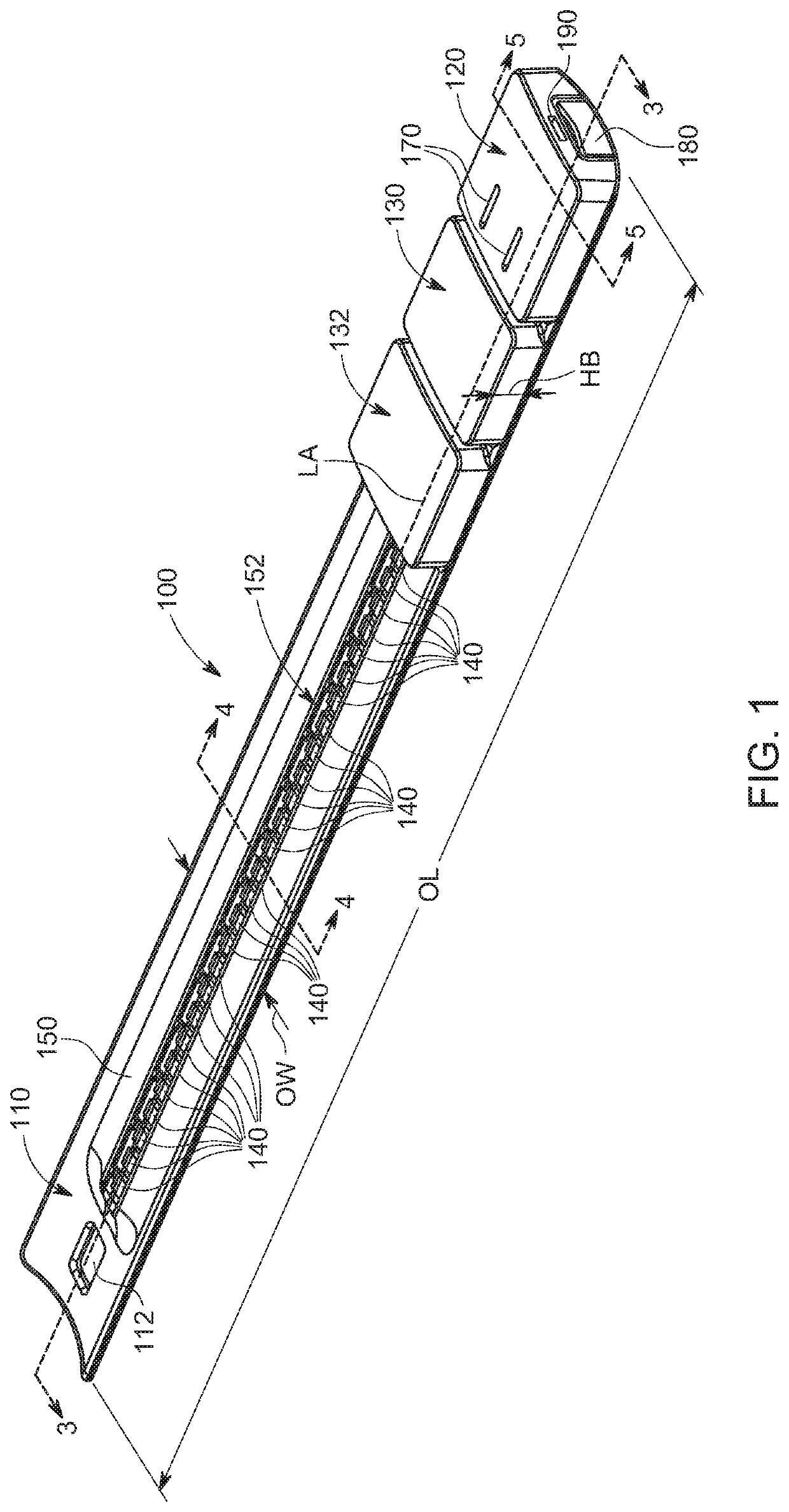
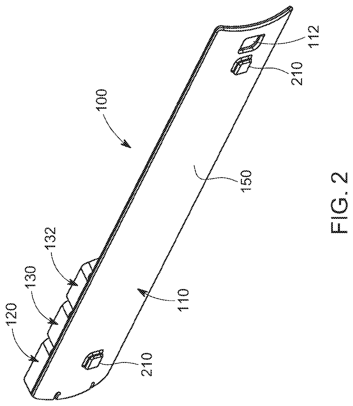
[0020]FIGS. 1 and 2 show and overview of a flexible strip light 100 according to an exemplary implementation. The strip light 100 consists of a base 110, having a rear through-slot 112 that can be used to attach a keyring, lanyard or hanger. There are also at least two projections on the bottom that can each enclose a high-strength, magnet 210 to allow the strip to be secured to a ferro-metallic surface. In various embodiments, the magnets 210 can be flush with the bottom surface of the strip light 110. The base 110 of the strip light 100 also includes an electronics module or pod 120 at an opposing, front end. A pair of battery pods 130 and 132 are provided adjacent to the electronics pod. Any acceptable rechargeable (or single-use) battery can be used—for example, lithium-based, NiMH-based and / or NiCad-based. As described below, the battery pair generate 1.5 Watts to operate the LED array. As described below, larger wattage outputs (e.g. 4.5-5 Watts, or, in some embodiments, small...


PUM


Abstract

This invention provides a flexible strip light, having a linear array of LEDs mounted in conjunction with a spring-loaded base (a strip of spring steel) that includes a cambered cross section. The camber is adapted to provide beam strength when it is arranged in an extended orientation. The camber otherwise forces the base to roll when the base is bent in a direction opposite the curl of the camber. The diameter of the rolled cylinder can vary. In general the diameter of the base conforms to the cross-sectional dimensions of an underlying curved or polygonal supporting member. The bend can be induced by manually grasping two points on the base surface and causing it to bend against the camber, or simply allowing inertia to generate a bend as the base is struck or slapped against the supporting member. The base and lighting array can be covered with a durable polymer.

Description

RELATED APPLICATIONS[0001]This application claims the benefit of U.S. Provisional Application Ser. No. 62 / 829,185, filed Apr. 4, 2019, entitled FLEXIBLE STRIP LIGHT WITH SPRING-LOADED BASE, the entire disclosure of which is herein incorporated by reference.FIELD OF THE INVENTION[0002]This invention relates to portable lighting devices and more particularly to lighting devices that provide a plurality of illumination sources in a line or strip.BACKGROUND OF THE INVENTION[0003]Lighting is a necessary aspect of many tasks. In photography and cinematography, the placement of lighting to directly illuminate a subject is often accomplished by dedicated, continuous-intensity lights and / or flashing strobes. However, many subjects require fill-in lighting to mitigate shadows and darkened areas and / or to further accentuate certain features. In some arrangements, the use of larger lights and flashes is also inconvenient or access to place such lighting may be limited. Thus, it is desirable to ...

Claims


Application Information

Patent Timeline
IPC IPC(8): F21V21/08F21V23/02F21V31/00F21V23/06H05K1/02F21V23/04H05K1/18H02J50/10F21Y103/10F21Y115/10F21V23/00F21V21/096H02J7/02
CPCF21V21/08F21V23/023F21V23/0464F21V23/06F21V31/005H05K1/028H05K1/181F21V21/0816F21V21/096F21V23/005F21Y2103/10F21Y2115/10H02J7/02H02J50/10H05K2201/10037H05K2201/10053H05K2201/10106H05K2201/10151H05K2201/10189F21S9/02F21S4/22H02J7/0042H02J7/342
Inventor TIROSH, UDI JOSEF
Owner SPIFFY VENTURES LTD
Learn More