Boosted converter for pulsed electric machine control

a technology of electric machine control and boosted converter, which is applied in the direction of dynamo-electric converter control, propulsion by batteries/cells, transportation and packaging, etc., can solve the problems of machine transition between high and low operating efficiency levels, low operation efficiency, and low efficiency of electric machine operation, so as to reduce rise and fall times, improve operation efficiency, and reduce pulse fall time

Active Publication Date: 2021-03-09
TULA ETECH INC
View PDF71 Cites 15 Cited by
  • Summary
  • Abstract
  • Description
  • Claims
  • Application Information

AI Technical Summary

Benefits of technology

[0010]The present application is directed toward pulsed control of electric machines, such as motors and generators, to improve operational efficiency. In a non-exclusive embodiment, such a pulsed-controlled machine includes a power supply, a stator with windings, a rotor of design dependent upon the motor topology, a machine controller configured to selectively operate the machine in a pulsed mode, and a power converter coupled between the power supply and the electric machine. The power converter is arranged to provide pulsed input power to the windings of the stator of the machine in response to the machine controller. In addition, the power converter may include a boost circuit. The boost circuit is arranged to reduce rise and fall times of the pulsed power relative to the rise and fall times of the pulsed power without the boost circuit. The boost circuit extracts at least some of a magnetic energy present in the electric machine at the end of a pulse to reduce the pulse fall time, stores at least some of the energy, and applies at least some of the energy at the beginning of a subsequent pulse to reduce the rise time. By reducing the rise and fall times of the pulsed power, the efficiency of the electric machine and overall electrical system is improved.

Problems solved by technology

As a result, machines typically operate at or near the highest levels of efficiency at certain times, while at other times, they operate at lower efficiency levels.
Outside these ranges, the operation of electric machine is less efficient.
As driving conditions change, the machine transitions between high and low operating efficiency levels as the rotor speed and / or torque changes.

Method used


Image

  • Boosted converter for pulsed electric machine control
  • Boosted converter for pulsed electric machine control
  • Boosted converter for pulsed electric machine control

Examples


Embodiment Construction

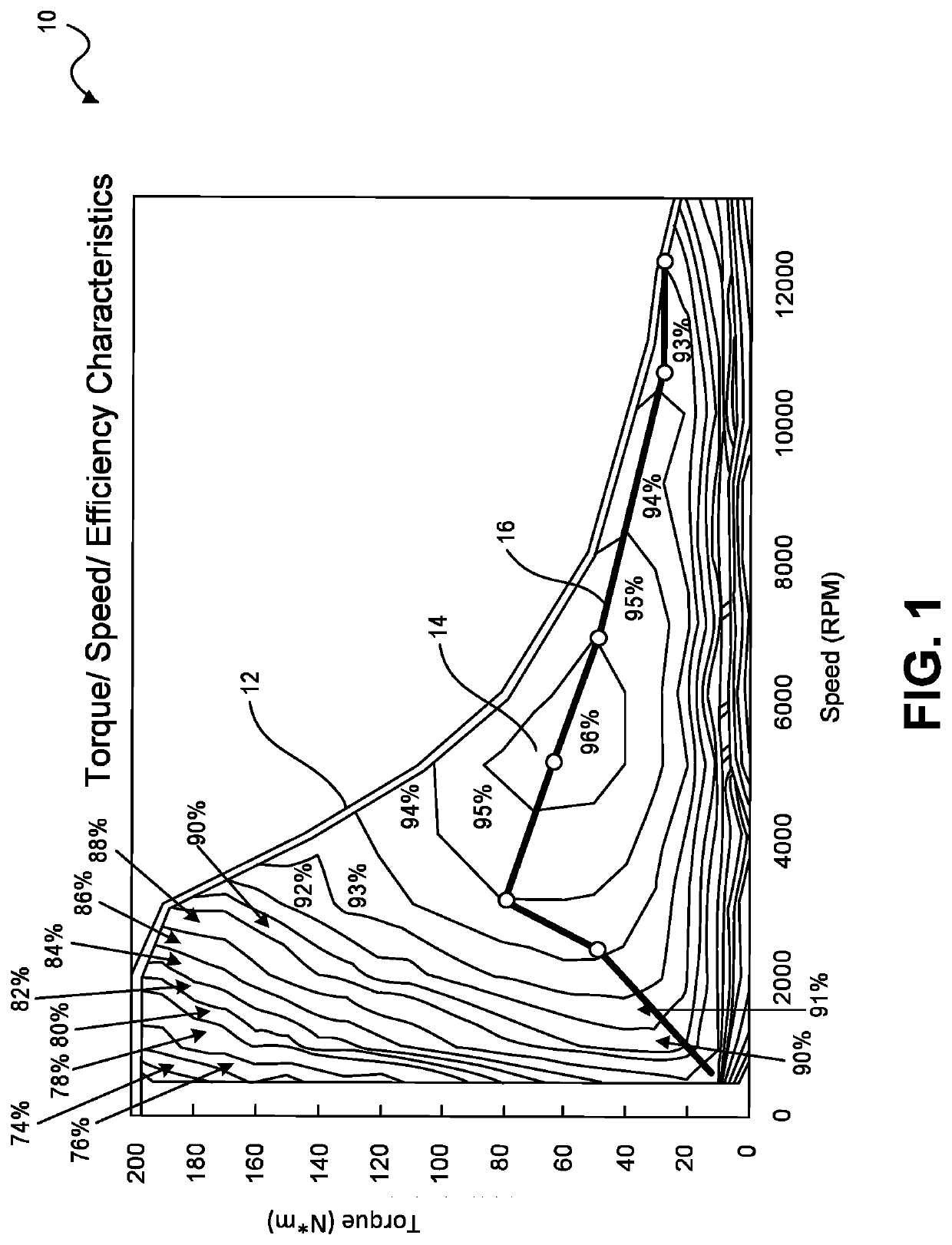
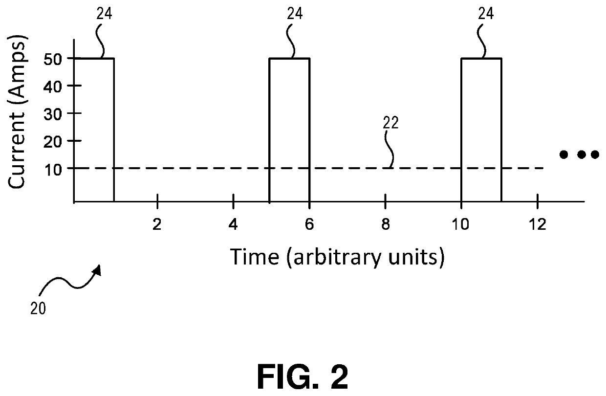
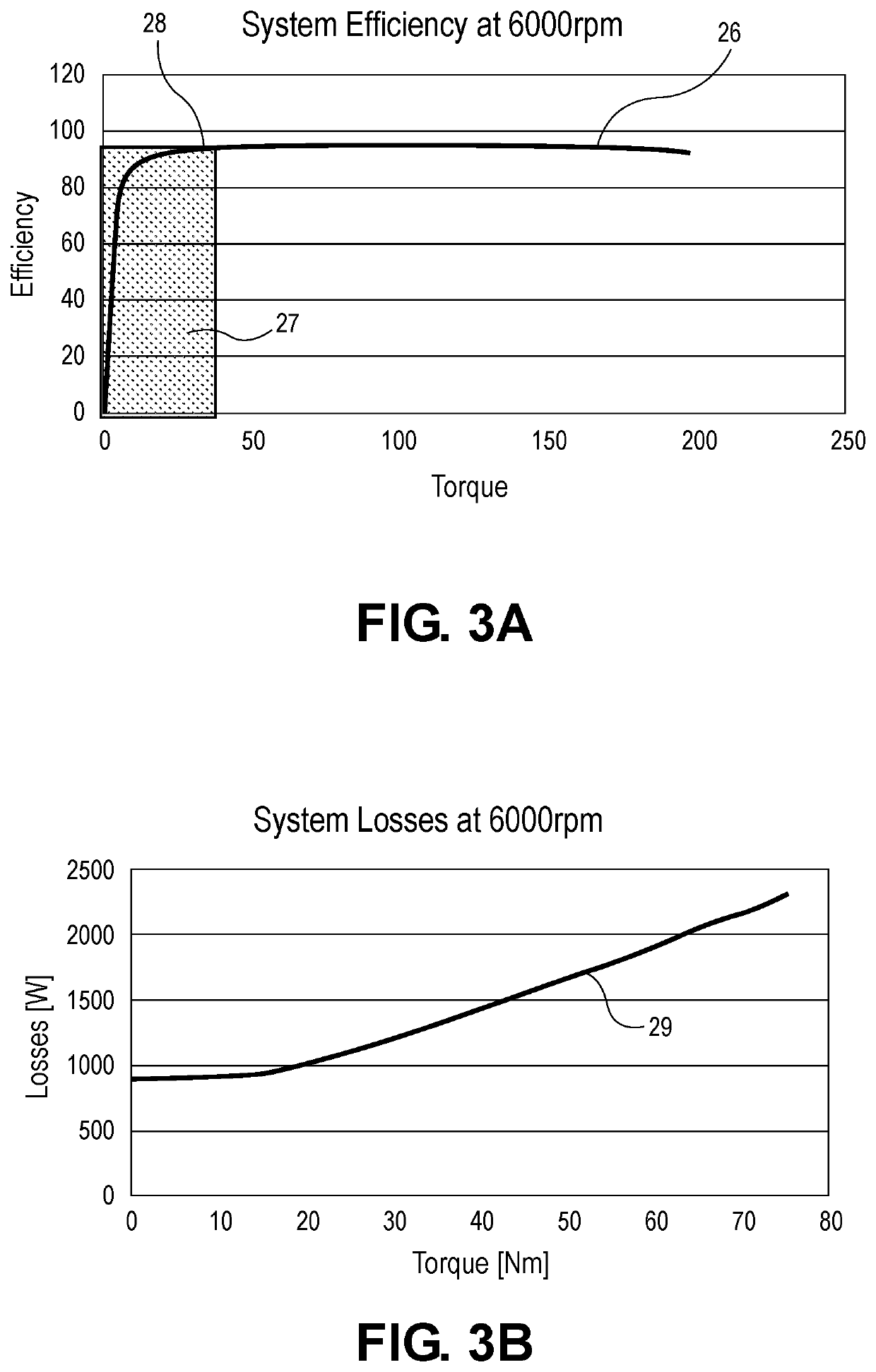
[0030]The present application relates generally to pulsed control of a wide variety of electric machines (e.g., electric motors and generators) that would otherwise be operated in a continuous manner By pulsed control, the machine is intelligently and intermittently pulsed on and off to both (1) meet operational demands while (2) improving overall efficiency. More specifically, under selected operating conditions, an electric machine is intermittently pulse-driven at more efficient energy conversion operating levels to deliver the desired average output more efficiently than would be attained by conventional continuous machine operation. Pulsed operation results in deliberate modulation of the electric machine torque; however, the modulation is managed in such a manner such that levels of noise or vibration are minimized for the intended application.

[0031]For the sake of brevity, the pulsed control of a wide variety of electric machines as provided herein is described in the context...


PUM


Abstract

A boost circuit is arranged to reduce rise and fall times of pulsed power used for pulsed control operation of electric machines. Magnetic energy present in the electric machine at the end of a pulse is extracted by the boost circuit to reduce the pulse fall time. The energy is stored by the boost circuit and then applied at the beginning of a subsequent pulse to reduce the rise time. By reducing rise and fall times compared to not using such a boost circuit, machine efficiency is improved.

Description

CROSS-REFERENCE TO RELATED APPLICATIONS[0001]This application claims priority of U.S. Provisional Application No. 62 / 819,097, filed on Mar. 15, 2019. This application also is a Continuation-in-Part of U.S. application Ser. No. 16 / 353,166 filed Mar. 14, 2019, which claims priority to U.S. Provisional Application Ser. No. 62 / 810,861 filed Feb. 26, 2019, U.S. Provisional Application Ser. No. 62 / 658,739 filed Apr. 17, 2018 and U.S. Provisional Application Ser. No. 62 / 644,912 filed Mar. 19, 2018. This application is further a Continuation of International Application No. PCT / US20 / 22262, filed Mar. 12, 2020. Each of the above listed provisional and non-provisional applications are incorporated by reference herein for all purposes.BACKGROUND OF THE INVENTION[0002]The present application relates generally to pulsed control of electric machines to selectively deliver a desired output in a more energy efficient manner, and more particularly, to a boosted converter circuit with improved rise a...

Claims


Application Information

Patent Timeline
Patent Type & Authority Patents(United States)
IPC IPC(8): H02P27/08
CPCH02P27/085H02P2201/09B60L15/007B60L50/51H02P21/02H02P23/02Y02T10/64Y02T10/70
Inventor MAZDA, BABAKTRIPATHI, ADYA S.CARVELL, PAUL
Owner TULA ETECH INC
Why Eureka
Try Eureka