Safety system, method and computer program for remotely controlled work vehicles

a safety system and work vehicle technology, applied in direction finders using radio waves, instruments, reradiation, etc., can solve problems such as system problems, system stress, and many work vehicles, so as to reduce the probability of all signals, and improve the accuracy of gnss coordinates

Active Publication Date: 2021-04-13
HUSQVARNA AB
View PDF17 Cites 0 Cited by
  • Summary
  • Abstract
  • Description
  • Claims
  • Application Information

AI Technical Summary

Benefits of technology

[0010]As has been described in the background section above, there is a need in the art for an automatic safety system that enables varying the safety distance between the work vehicle and the wireless remote control to take into account both a minimum and a maximum safety distance interval. The present disclosure remedies this by keeping the wireless remote control and the vehicle unit in constant communication with each other, with the distance between them being determined periodically. In other words, the wireless remote control will always be inside the protective field of the vehicle unit as long as the wireless remote control and the vehicle unit are within signaling range of each other. Since the wireless remote control is always in communication with the vehicle unit as long as they remain within range of each other, it is possible to introduce distance intervals where different types of control signals are transmitted to the drive control mechanism without having to introduce additional measurement systems, such as e.g. short range radars. In particular, the safety system can be arranged to have an upper limit on the allowed distance, which effectively eliminates the risk of the wireless remote control losing contact with the vehicle unit. This prevents the work vehicle from moving out of range of the wireless remote control, which is a particularly useful feature if the work vehicle is operating in a semi-autonomous mode. Additionally, a need to be able to determine the distance independent of transmitter strength or antenna shape has been identified. The present disclosure addresses this need by relying on information within signals, and possibly information available within or generated by system components, rather than physical properties of the signals, such as e.g. signal power.
[0013]According to some aspects, the vehicle unit is arranged to determine the first distance using two-way ranging time of flight based on a time stamp based on the information relevant for positioning of the work vehicle that is time stamped at an initial time of the two-way ranging and a and a time stamp based on a received signal that is time stamped at a finishing time of the two-way ranging. The use of a local coordinate system associated with the time of flight based safety system draws on the predetermined spatial relationships between the point on the vehicle unit where the signal initiating the two-way ranging is located with respect to the work vehicle as well as between the transceiver and the wireless remote control unit. The distance in the local system from the origin to the point on the vehicle unit is zero (or some known arbitrary constant) by definition. The time stamp associated with the signal initiating the two way ranging is thus all the information needed to determine the position of the work vehicle at the time of the time stamp, since it is zero by definition. A time stamp requires a minimal amount of data to be stored and / or processed. The information relevant for positioning of the work vehicle may thus only comprise one or more time stamps. Both time stamps can then be used to determine the distance signals have travelled and the work vehicle is stopped if the work vehicle enters the predetermined distance interval. The associated time stamps, in addition to requiring a minimal amount of data to be transferred, may also be used to check the status of the communication link between the vehicle unit and the operator unit. By adding time stamps it is possible to determine if the safety system is receiving reliable results by comparing the time stamps with the present time. Too long time between measurements could indicate problems and the safety system is preferably arranged to take actions to handle this.
[0016]According to some aspects, the vehicle unit comprises a first receiver arranged to receive a vehicle coordinate signal comprising the GNSS coordinates of the position of the work vehicle. The operator unit comprises a second receiver arranged to receive an operator coordinate signal comprising the GNSS coordinates of the position of the wireless remote control unit. According to some further aspects, the first and second receivers are further arranged to receive corrective information, the corrective information being based on predetermined GNSS coordinates of at least one reference point. The vehicle unit is further arranged to improve the accuracy of the GNSS coordinates of the positions of the work vehicle and the wireless remote control unit based on the corrective information. The first and second receivers enable an implementation of a safety system based on coordinates from a global navigation satellite system. In other words, the transceivers enable an implementation of a global coordinate system based on the received GNSS coordinates. The corrective information improves the accuracy of the GNSS coordinates.
[0017]According to some aspects, the information relevant for positioning of the work vehicle comprises information relating to a second position of the work vehicle, wherein the spatial relationship further relates to a second distance between the work vehicle and the wireless remote control unit based on the second position. The predetermined criterion further comprises the second distance falling within a second predetermined distance interval. Determining two distances provides redundancy. In other words, if one determined position indicates a problem in determining that distance, the other determined distance may provide the necessary information for continued operational use of the safety system. By determining two distances, it is possible to arrange the safety system to detect if the operator (holding the wireless remote control unit) is standing in front or behind the work vehicle. In aspects based on time of flight for distance determination between the work vehicle and the wireless remote control unit, additional determined distances reduce the impact of human blocking, wherein human blocking refers to the time delay associated with a signal passing through the human body. Signals travelling along different paths will be affected differently by human blocking and more determined distances may be used to reduce the probability that all signals will be affected by human blocking.
[0018]According to some aspects, the vehicle unit and the wireless remote control unit each comprises direction detection means arranged to determine a direction of the work vehicle and the wireless remote control unit, respectively, wherein the vehicle unit is further arranged to determine a relative direction between the determined directions of the work vehicle and the wireless remote control unit. The vehicle unit is also arranged to stop the work vehicle based on a predetermined relative direction criterion. This enables stopping the work vehicle if an operator holding the wireless remote control unit is facing in a direction deemed unsafe. For instance, the work vehicle may be stopped if the operator has his / her back to the work vehicle. It further enables detecting if the operator is at risk of losing focus of the task of operating the work vehicle, e.g. by rotating in a direction away from facing the work vehicle.
[0024]According to some aspects, determining the spatial relationship further comprises determining a first and a second distance between the work vehicle and the wireless remote control unit. Periodically determining if the spatial relationship meets a predetermined criterion further comprises, for each of the first and second distances, determining if at least one of the first and second distances falls within a predetermined distance interval. Providing a second control signal to the work vehicle further comprises arranging the at least one second control signal to stop the work vehicle if at least one of the first and second distances fall within the predetermined distance interval and fall within a second predetermined distance interval. The first and distances provide redundancy to the method. By determining two distances between the work vehicle and the wireless remote control unit, accuracy can be improved with respect to only determining a single distance. By also providing a second predetermined distance interval, the method can take into account the possibility of one of the two determined distances not being properly provided and that the accuracy related to having two distances is lost.

Problems solved by technology

Many work vehicles are also subjected to various types of stress, e.g., vibrations and noise.
However, the size and weight of many of the remotely operated work vehicles combined with the fact that they are mobile implies that there is a risk of injury due to collision between the work vehicle and an operator of the vehicle.
Such systems often suffer from problems due to interference or limitations in the area that is monitored.
While safety systems based on RFID technology is an improvement over not using any type of radio based safety system, there are drawbacks from using RFID technology, e.g., from characteristics of the antenna of the RFID tag.
The power radiated from an antenna in the RFID tag is not isotropic, which means that determining the distance to the antenna is complicated by the lack of isotropic radiation.
Furthermore, RFID tag-based distance determining systems depending on a Radio Signal Strength Indicator, RSSI, do not work very well for longer distances, i.e., over about 3 m, because the received signal power drops exponentially with distance.

Method used


Image

  • Safety system, method and computer program for remotely controlled work vehicles
  • Safety system, method and computer program for remotely controlled work vehicles
  • Safety system, method and computer program for remotely controlled work vehicles

Examples


Embodiment Construction

[0037]In the following description the wording “arranged at” is to be understood as comprising “arranged on” and “arranged in” as well as being “arranged in proximity to”, e.g. by the use of a distancing element, unless otherwise stated. For instance, a transceiver “arranged at” the work vehicle may be arranged partially or completely in the work vehicle. An example of “partially in” could be the transceiver being arranged in the work vehicle with an antenna of the transceiver extending outside of the work vehicle. The transceiver may also be arranged on the work vehicle, e.g. mounted on a surface of the work vehicle. It is sometimes preferable to mount e.g. a signal transmitting or receiving unit at a distance from the work vehicle to reduce the impact of signal obstruction from dirt and work vehicle components and “arranged at” is to be understood to include such cases as well.

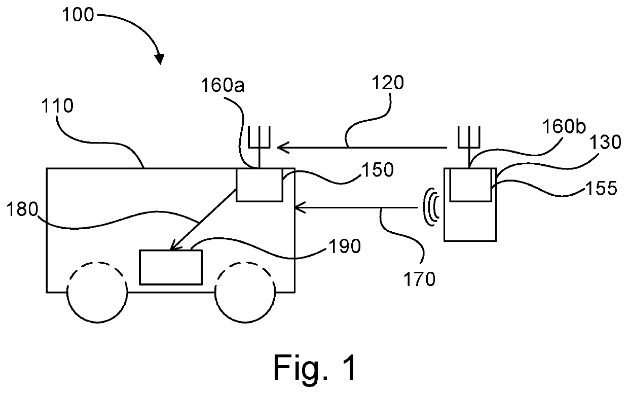
[0038]FIG. 1 illustrates a safety system 100 for a remotely operated work vehicle 110. FIG. 1 illustrates...


PUM


Abstract

The present disclosure relates to a safety system (100) for a remotely operated work vehicle (110). The safety system (100) works by continuously establishing a spatial relationship between the work vehicle (110) and a wireless remote control unit (130), wherein at least part of the information needed to establish the spatial relationship is carried as data in signals. The established spatial relationship is then used to control the work vehicle (110).

Description

TECHNICAL FIELD[0001]The present disclosure relates to safety systems for remotely controlled work vehicles, methods performed in safety systems for remotely controlled work vehicles and corresponding computer programs.BACKGROUND ART[0002]Remote operation of work vehicles offers many advantages in various work environments. For instance, by operating the work vehicle remotely, accommodation for an operator in or on the work vehicle is no longer necessary. Many work vehicles are also subjected to various types of stress, e.g., vibrations and noise. By remotely operating the work vehicle, the impact of such stresses on the operator can be reduced or eliminated.[0003]However, the size and weight of many of the remotely operated work vehicles combined with the fact that they are mobile implies that there is a risk of injury due to collision between the work vehicle and an operator of the vehicle. One of the most direct ways to reduce the risk of injury is to provide either the work vehi...

Claims


Application Information

Patent Timeline
Patent Type & Authority Patents(United States)
IPC IPC(8): G05D1/00G08C17/02E02F9/20G01S13/76G01S3/14G01S5/02G01S1/24B60W60/00G05D1/02
CPCG05D1/0055E02F9/205G01S3/14G01S5/0284G01S13/765G05D1/0016G05D1/0022G08C17/02G01S1/24G05D2201/0202G08C2201/32G08C2201/91G05D1/0011
Inventor IDBRANT, MARCUSELOFSSON, KRISTIANSIHM, HENRIK
Owner HUSQVARNA AB
Why Eureka
Try Eureka