Method for determining the deflection of a wind turbine blade using the wind turbine blade's known modal profile

a technology of wind turbine blade and modal profile, which is applied in the direction of distance measurement, instruments, and using reradiation, can solve the problems of additional complications in the area of cost and constructional challenges, the blade damage, and the event of complete failure of the wind turbine structure, so as to increase the processing speed of the method and improve the system's responsiveness

Active Publication Date: 2021-04-27
LM WP PATENT HLDG
View PDF10 Cites 0 Cited by
  • Summary
  • Abstract
  • Description
  • Claims
  • Application Information

AI Technical Summary

Benefits of technology

[0012]By utilizing a known modal profile of a wind turbine blade in the blade deflection monitoring system, the accuracy of the deflection monitoring system can be improved. Using a single distance measurement between known positions on a blade, an accurate blade deflection profile can be calculated based on the predicted mode shapes of the wind turbine blade. Accordingly, the accuracy of the deflection monitoring system can be improved, as it can operate using only a single distance measurement.
[0014]Determining a blade deflection profile allows for the calculation of the location of a blade tip end. Accordingly, it is possible to estimate if a blade tip will be deflected towards a wind turbine tower, and to judge whether such deflection exceeds a safety margin for the blade tip striking the wind turbine tower. It will be understood that the method may further comprise the step of generating a control signal based on said calculation of whether the deflection of said wind turbine blade exceeds a safety threshold for a tower strike. Such a control signal may be used as an input to a wind turbine control system, which may be operable to adjust wind turbine performance based on said calculation, e.g. to adjust a pitch angle of a wind turbine blade to reduce the risk of a tower strike, or to stop turbine operation to prevent a tower strike.
[0019]During blade rotation, the blade may bend in different directions resulting in interruptions or disruptions of the wireless communication link between the root and the tip end. By providing multiple possible communication links, accordingly the distance measurement can be performed between the root and tip locations having the best quality and / or strength of signal, which can result in a more accurate distance measurement.
[0027]Positioning a second tip location at the node of the second mode shape of the blade allows for the first and second modes of the blade to be decoupled from each other. As it is possible to isolate the effect of the second mode shape from the first mode shape, accordingly, the accuracy of the blade deflection calculation can be improved
[0043]By pre-calculating the mode amplitude, mode shape, and / or tip location for at least some measured distances, the processing speed of the method may be increased, leading to a greater responsiveness of the system.

Problems solved by technology

Such deflection can be so extreme as to cause the wind turbine blade tips to strike the tower of the wind turbine, thereby causing damage to the blade or event complete failure of the wind turbine structure.
Such solutions present additional complications in the area of cost and constructional challenges.
However, one of the challenges with such systems is ensuring continuous, reliable, and accurate operation of the monitoring systems.

Method used


Image

  • Method for determining the deflection of a wind turbine blade using the wind turbine blade's known modal profile
  • Method for determining the deflection of a wind turbine blade using the wind turbine blade's known modal profile
  • Method for determining the deflection of a wind turbine blade using the wind turbine blade's known modal profile

Examples


Embodiment Construction

[0061]Embodiments of the invention will now be described, by way of example only, with reference to the accompanying drawings:

[0062]It will be understood that elements common to the different embodiments of the invention have been provided with the same reference numerals in the drawings.

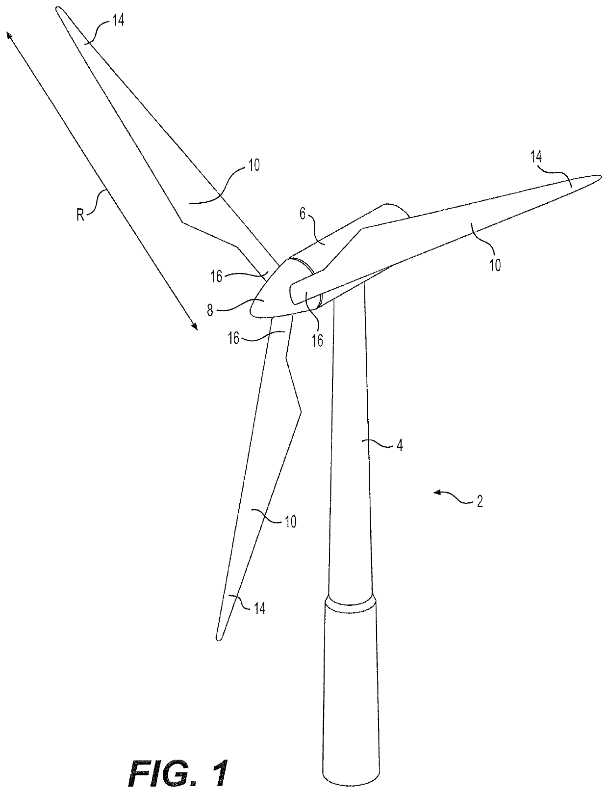
[0063]FIG. 1 illustrates a conventional modern upwind wind turbine 2 according to the so-called “Danish concept” with a tower 4, a nacelle 6 and a rotor with a substantially horizontal rotor shaft. The rotor includes a hub 8 and three blades 10 extending radially from the hub 8, each having a blade root 16 nearest the hub and a blade tip 14 furthest from the hub 8. The rotor has a radius denoted R.

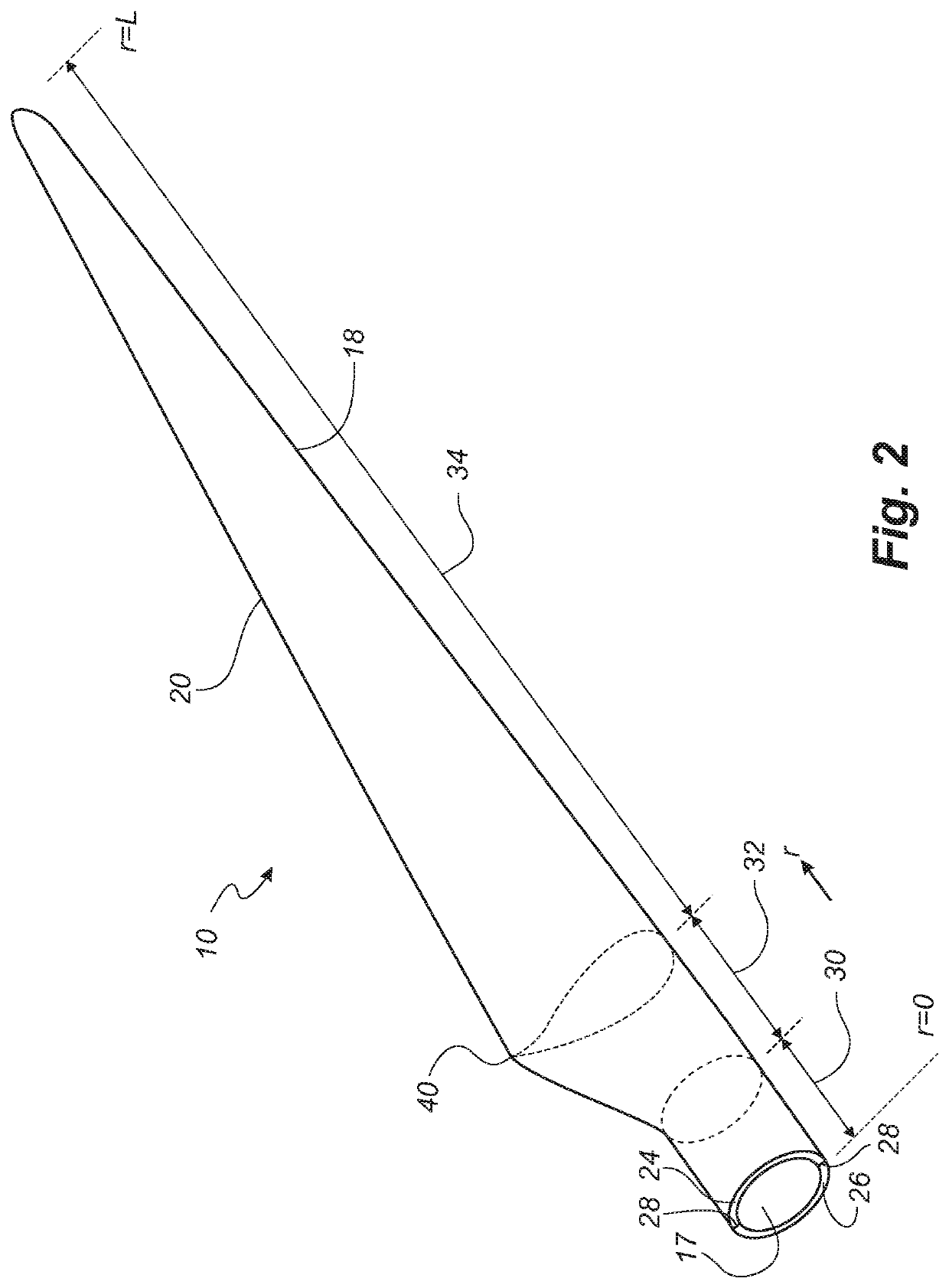
[0064]FIG. 2 shows a schematic view of a wind turbine blade 10. The wind turbine blade 10 has the shape of a conventional wind turbine blade and comprises a root region 30 closest to the hub, a profiled or an airfoil region 34 furthest away from the hub and a transition region 32 between the root region 30...


PUM


Abstract

A method for the determination of the deflection of a wind turbine blade is provided. A distance between at least one root location towards a root end of the wind turbine blade and at least one tip location towards a tip end of the wind turbine blade is measured. A blade deflection profile is then calculated based on the measured distance between the root and tip locations and a known modal profile of the wind turbine blade.

Description

[0001]This is a National Phase Application filed under 35 U.S.C. 371 as a national stage of PCT / EP2015 / 070744, filed Sep. 10, 2015, an application claiming the priority benefit of EP 14184601.4 filed Sep. 12, 2014, the content of each of which is hereby incorporated by reference in its entirety.FIELD OF THE INVENTION[0002]The present invention relates to a system and method for determining a deflection of a wind turbine blade.BACKGROUND OF THE INVENTION[0003]During operation of a wind turbine, considerable forces act on the blades of the wind turbine, bending and deflecting the blades. Such deflection can be so extreme as to cause the wind turbine blade tips to strike the tower of the wind turbine, thereby causing damage to the blade or event complete failure of the wind turbine structure.[0004]In efforts to reduce the risk of tower strike, wind turbine manufacturers have utilised different techniques in wind turbine construction. In some cases, wind turbines use pre-bent blades, ha...

Claims


Application Information

Patent Timeline
Patent Type & Authority Patents(United States)
IPC IPC(8): F03D17/00F03D7/04F03D1/06F03D7/02G01C3/06G01S11/02
CPCF03D17/00F03D1/0675F03D7/0224F03D7/045G01C3/06G01S11/02F05B2260/83F05B2270/17F05B2270/33F05B2270/821F05D2240/307F05D2260/81Y02E10/72
Inventor BÆK, PETERKLITGAARD, MICHAELBYSKOV, CLAUS
Owner LM WP PATENT HLDG
Why Eureka
Try Eureka