Method for regulating the output pressure of a hydraulic drive system, use of the method and hydraulic drive system

a hydraulic drive system and output pressure technology, applied in the direction of machines/engines, positive displacement liquid engines, mechanical apparatuses, etc., can solve the problems of insufficient accuracy, inconvenient operation, and high cost of tachometers, and achieve the effect of easy and robust determination, robust and precise control arrangement according to the invention

Active Publication Date: 2021-05-11
VOITH PATENT GMBH
View PDF18 Cites 1 Cited by
  • Summary
  • Abstract
  • Description
  • Claims
  • Application Information

AI Technical Summary

Benefits of technology

[0017]This allows for a rough adjustment of the setpoint rotational speed and the adjustment range is thus drastically reduced.
[0022]According to the present invention, the error rotational speed—also referred to as corrective signal—is determined as control deviation from the setpoint pressure value (reference variable) and the actual pressure value (regulating variable) and adjoining regulating amplifier, for example a PI or PID controller. In addition, the actual pressure value is determined by way of a pressure sensor. This process step makes possible the compensation of lossy and non-linear characteristics such as compression and decompression effects in the hydraulic drive system. The necessary corrective signal is however small relative to the maximum possible rotational speed amplitude of the hydraulic drive system and can therefore be easily and robustly determined with the regulating amplifier. Since the error rotational speed does not illustrate the entire value range of the rotational speed of the hydraulic drive system, the amplification factors of the regulating amplifier can be robustly selected.
[0023]In the event that the hydraulic drive system is impacted by an external load—for example a force caused by a die cushion or a tool in a machine tool—the corrected rotational speed calculated from the comparison between setpoint pressure value and actual pressure value has a comparatively small part in the rotational speed control. The control arrangement according to the invention is therefore robust and precise.
[0029]In another embodiment, the at least one parameter is determined by way of sensor elements in order to calculate the second setpoint rotational speed component. The parameter is for example an actuator speed or an actuator travel path or respectively an element speed or an element travel path. By way of a simple calculation conclusions can be reached from this parameter, regarding the volume flow, thus considerably improving regulating of the output pressure.

Problems solved by technology

Tachometers are expensive and inaccurate.
The method of pressure regulation described in the current state of the art is disadvantageous for a user with significant and variable volume flow in as far as regulating the pressure for large work areas is too inaccurate.
As a model for the actual torque the actual current is used, since an accurate torque measurement in practice is not feasible or requires very expensive torque sensors.

Method used


Image

  • Method for regulating the output pressure of a hydraulic drive system, use of the method and hydraulic drive system
  • Method for regulating the output pressure of a hydraulic drive system, use of the method and hydraulic drive system
  • Method for regulating the output pressure of a hydraulic drive system, use of the method and hydraulic drive system

Examples


Embodiment Construction

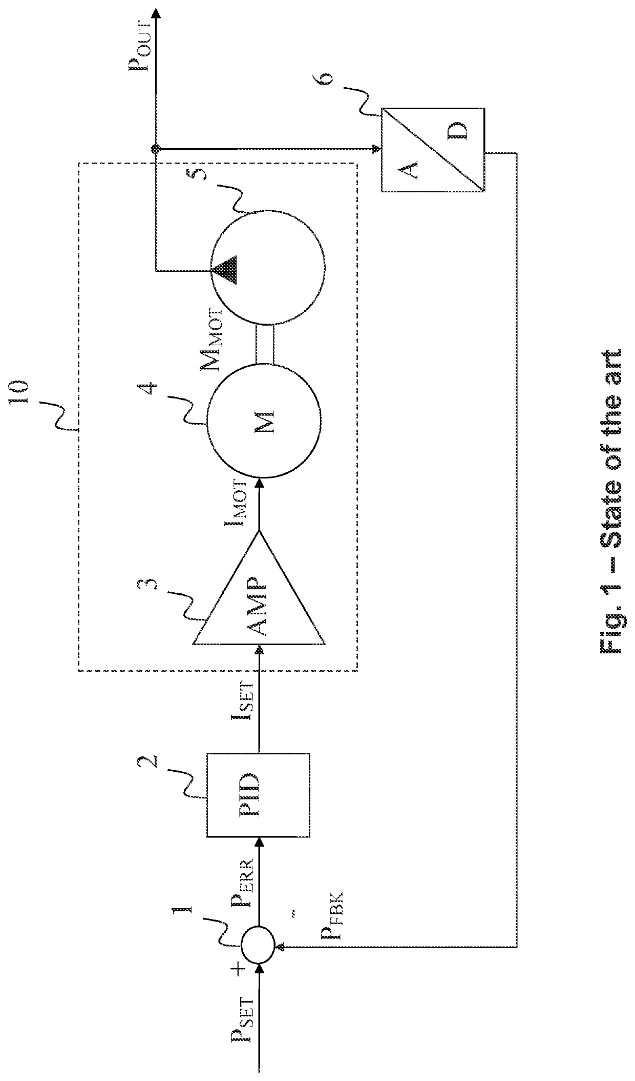
[0046]FIG. 1 shows a regulating system for output pressure POUT of a hydraulic drive system 10 according to a known method, as described for example in U.S. Pat. No. 6,379,119 B1. Hydraulic drive system 10 consists of a power amplifier 3, an electromotive drive 4 and a hydraulic pump 5. Hydraulic pump 5 provides an output pressure POUT at its outlet, with which for example a pull-push device as illustrated for example in FIG. 7 in the embodiment of a deep draw device 8 is driven.

[0047]According to FIG. 1, regulating of output pressure POUT occurs on the basis of an idealized linear relationship between the physical dimensions of pressure P, conveying volume QP of hydraulic pump 5 determined by its size and a torque M by determining of set and actual values of a motor current IMOT as a control variable.

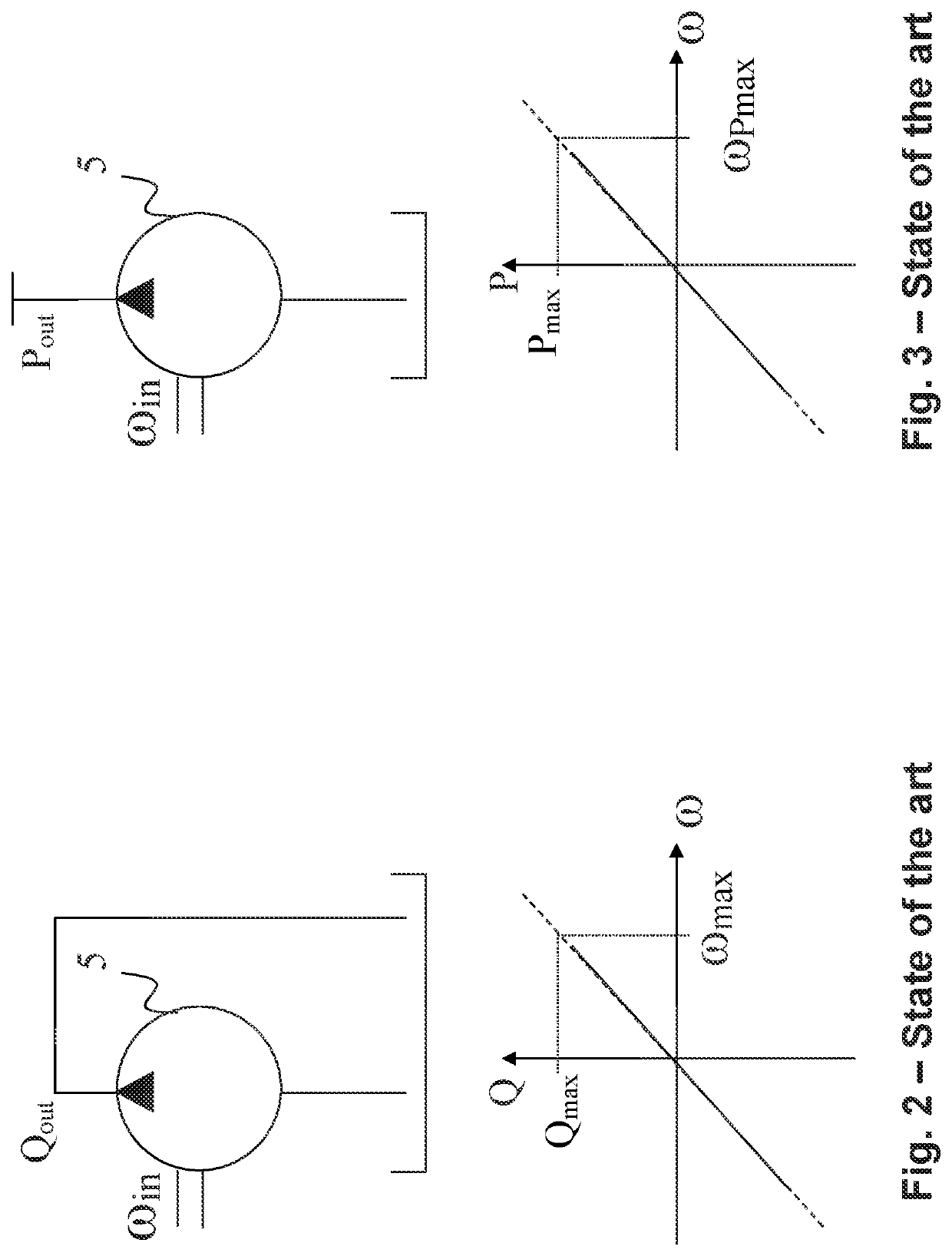
[0048]The following hydrostatic load torque applies for an ideal displacement pump as an example for a hydraulic pump 5 which is to be viewed without friction and losses at the sealing...


PUM

PropertyMeasurementUnit
pressureaaaaaaaaaa
rotational speedaaaaaaaaaa
volume flowaaaaaaaaaa

Abstract

A method for regulating output pressure of a hydraulic drive system by using a rotational speed as the actuating variable. The method includes determining a setpoint rotational speed main component of motor drive as a pilot control signal, determining an error rotational speed as a regulating deviation from a comparison of an actual pressure value of the hydraulic drive system and a setpoint pressure value of the hydraulic drive system and adjoining regulating amplifier, adding the determined setpoint rotational speed main component to the determined error rotational speed to create the setpoint rotational speed as the actuating variable, and converting the created setpoint rotational speed into an input rotational speed of the motor drive to drive the hydraulic drive system at the converted rotational speed in order to generate regulated output pressure of the hydraulic drive system which represents actual pressure value.

Description

CROSS REFERENCE TO RELATED APPLICATIONS[0001]This is a continuation of PCT application No. PCT / EP2018 / 070833, entitled “METHOD FOR REGULATING THE OUTPUT PRESSURE OF A HYDRAULIC DRIVE SYSTEM, USE OF THE METHOD AND HYDRAULIC DRIVE SYSTEM”, filed Aug. 1, 2018, which is incorporated herein by reference.BACKGROUND OF THE INVENTION1. Field of the Invention[0002]The present invention relates to a method for regulating the output pressure of a hydraulic drive system, use of the method, and a hydraulic drive system. The present invention may be used for hydraulic systems in pull-push forming devices, for example in a deep drawing device, preferably for active hydromechanical drawing.2. Description of the Related Art[0003]A hydraulic drive system, also referred to as a hydraulic drive can be produced by using a pump and a variable speed drive. Herein, the fluid flow from or respectively to an actuator, for example a hydraulic cylinder is regulated directly through the utilized pump and not th...

Claims


Application Information

Patent Timeline
Patent Type & Authority Patents(United States)
IPC IPC(8): F04B49/06B21D24/14F04B17/03
CPCF04B49/06B21D24/14F04B17/03F04B49/065F04B2203/0209F04B2205/05F04B2205/09F15B2211/20515F15B2211/20538F15B2211/6309F15B2211/633F15B2211/6651F15B2211/6653F15B2211/6654B29C51/46F04B49/08F04B49/20
Inventor BRAHMER, BERT
Owner VOITH PATENT GMBH
Why Eureka
Try Eureka