
Vertical electrode decoupling/bypass capacitor

a technology of bypass capacitor and vertical electrode, applied in the direction of fixed capacitor terminal, stacked capacitor, fixed capacitor details, etc., can solve the problems of mainly generating such noise in switching integrated circuits, power supplies and regulators, oscillators and amplifier circuits, etc., and achieve the problem of providing effective decoupling solutions

Active Publication Date: 2021-05-11
KYOCERA AVX COMPONENTS CORP
View PDF25 Cites 1 Cited by
  • Summary
  • Abstract
  • Description
  • Claims
  • Application Information

AI Technical Summary

Benefits of technology

The solution provides a low-profile capacitor with improved broadband frequency performance and reduced insertion loss, effectively addressing the need for miniaturization and increased functionality while maintaining low inductance, thus enhancing signal integrity and noise reduction in high-speed environments.

Problems solved by technology

Such problems comprise transient noise and reflect the supply transient induced by the chip itself on the decoupling capacitor when various clocks fire on-chip and drive on-chip capacitance associated with that event (such as address decoding).
In RF circuitry, oscillators and amplifier circuits generate such noise.
In the digital environment, the switching integrated circuits, power supplies and regulators mainly generate such noise, often in the form of a voltage ripple.
Thus, the broader range of frequencies to be addressed, the more problematic in providing effective decoupling solutions.

Method used


Image

  • Vertical electrode decoupling/bypass capacitor
  • Vertical electrode decoupling/bypass capacitor
  • Vertical electrode decoupling/bypass capacitor

Examples


Embodiment Construction

[0023]It is to be understood by one of ordinary skill in the art that the present discussion is a description of exemplary embodiments only, and is not intended as limiting the broader aspects of the present invention.

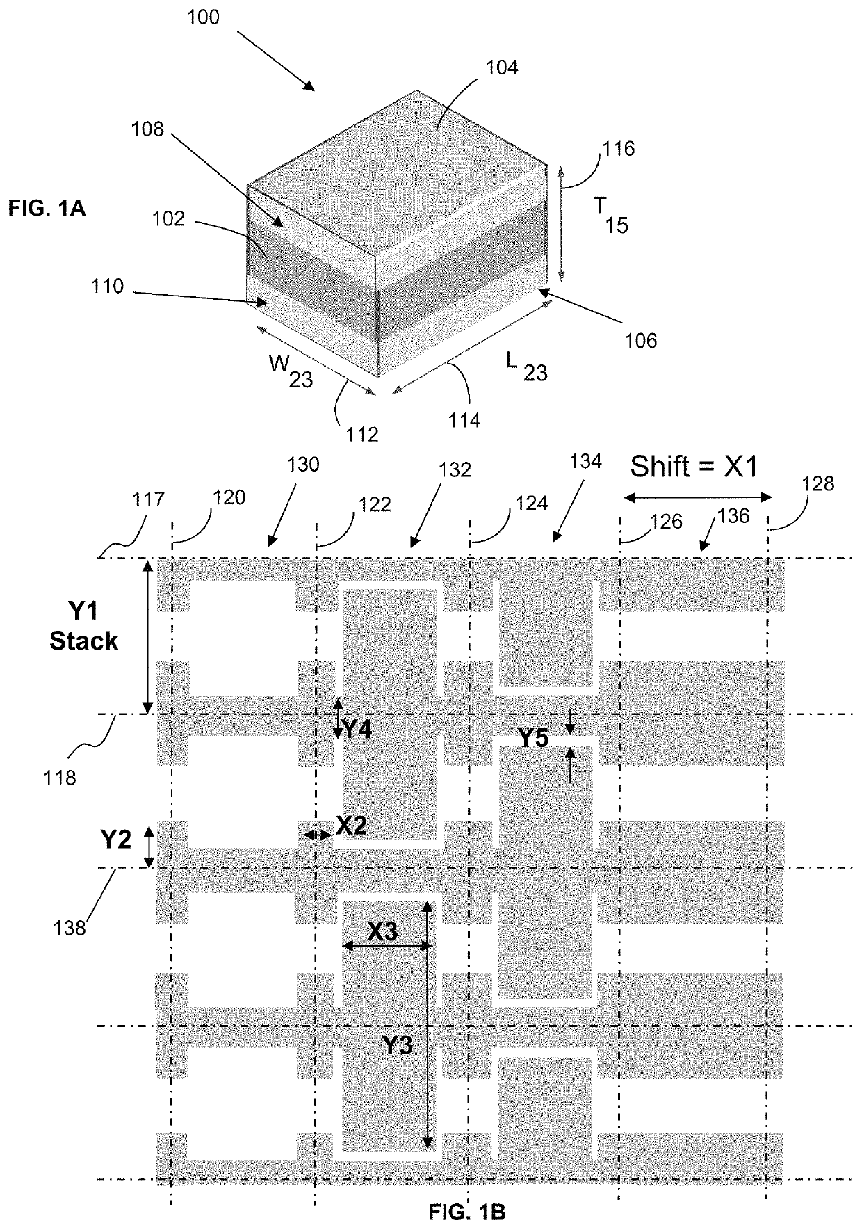
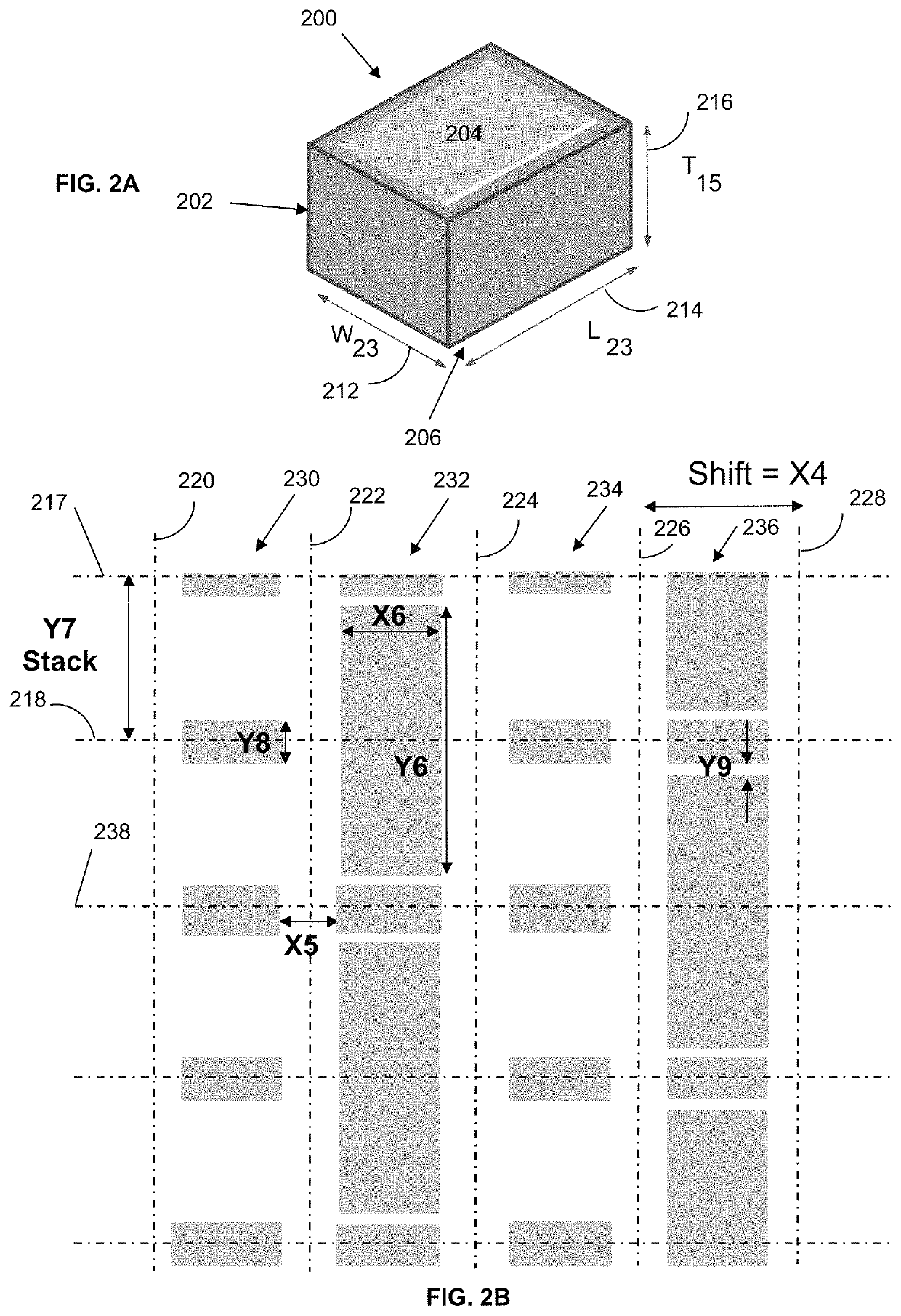
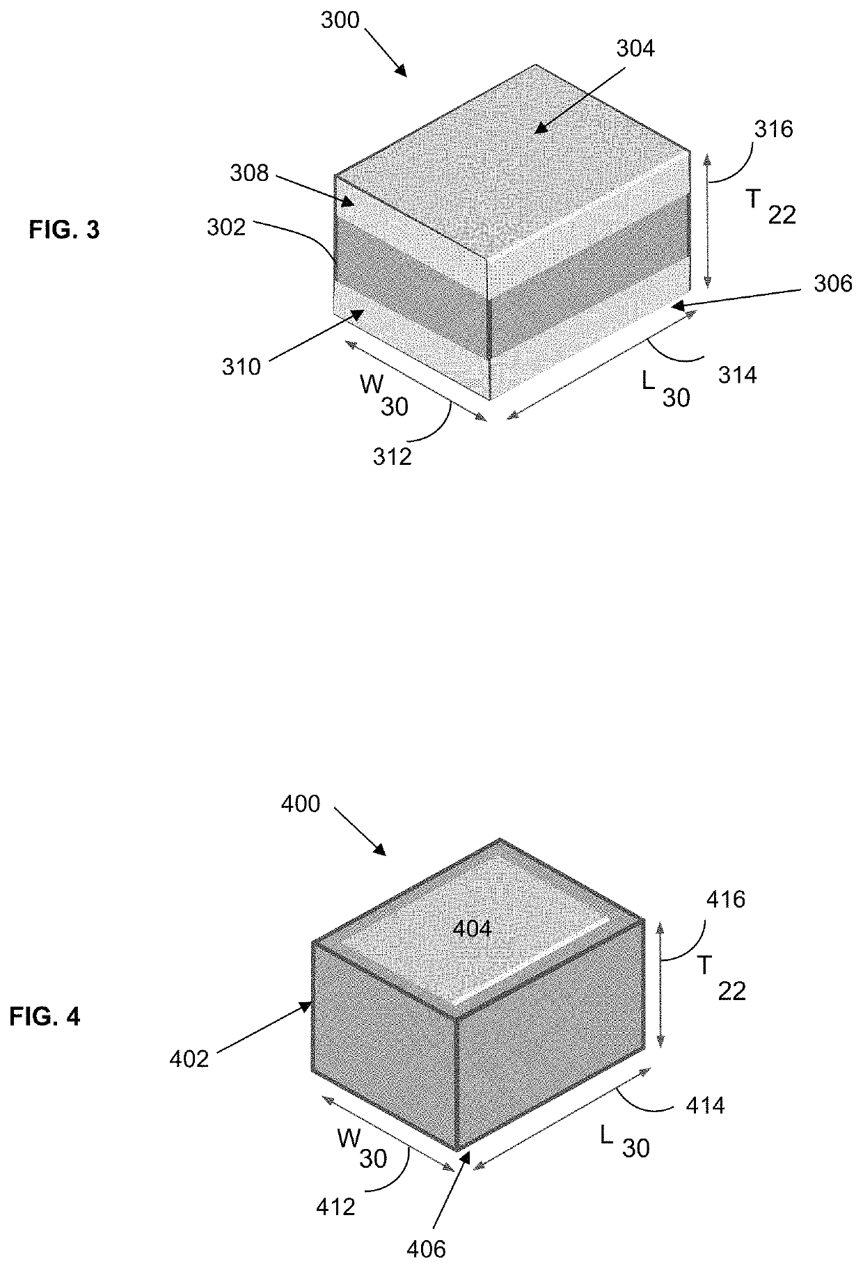
[0024]Generally speaking, the present invention is directed to a capacitor, in particular a decoupling / bypass capacitor, containing vertical electrodes. In particular, the electrode configuration can allow for the formation of a low-profile capacitor, for instance similar to a single layer capacitor. The present inventors have discovered that the electrode configuration described herein can allow for a stable performance over a broad range of frequencies. In particular, the electrode configuration can allow for minimal insertion loss over a broad range of frequencies.

[0025]The present invention includes a multilayer ceramic capacitor that contains a plurality of capacitive elements within a single, unitary package. The capacitor includes a top surface and a bottom surf...


PUM

PropertyMeasurementUnit
thicknessaaaaaaaaaa
thicknessaaaaaaaaaa
thicknessaaaaaaaaaa

Abstract

The invention is directed to a multilayer ceramic capacitor comprising a top surface and an opposing bottom surface and four side surfaces that extend between the top and bottom surfaces, a main body formed from a plurality of dielectric layers and a plurality of internal electrode layers alternately arranged, and external terminals electrically connected to the internal electrode layers wherein a first external terminal is disposed along the top surface and a second external terminal is disposed along the bottom surface. The internal electrode layer includes a first electrode electrically connected to the first external terminal and a second counter electrode electrically connected to the second external terminal, wherein the first electrode includes a central portion extending from the first external terminal toward the second external terminal and wherein the central portion extends 40% to less than 100% a distance from the first external terminal to the second external terminal.

Description

CROSS-REFERENCE TO RELATED APPLICATION[0001]The present application claims filing benefit of U.S. Provisional Patent Application Ser. No. 62 / 645,411 having a filing date of Mar. 20, 2018, and which is incorporated herein by reference in its entirety.BACKGROUND OF THE INVENTION[0002]For some time, the design of various electronic components has been driven by a general industry trend toward miniaturization, as well as increased functionality. In such regard, a need exists for ever smaller electronic components having improved operating characteristics. For example, some applications would benefit from the ability to have improved operating characteristics even if existing size is maintained. One such characteristic could be CV ratings for capacitors, which generally reflect the product of the capacitance of a device and the level of voltage it can handle. Other desirable characteristics may involve stable performance over an ever-increasing broad range of frequencies.[0003]As such ra...

Claims


Application Information

Patent Timeline
Patent Type & Authority Patents(United States)
IPC IPC(8): H01L23/34H01G4/012H01G4/232H01L23/66H01G4/30H01L23/00
CPCH01G4/012H01G4/232H01G4/30H01L23/66H01L24/48H01L2223/6666H01L25/16
Inventor HORN, JEFFREY A.BEROLINI, MARIANNE
Owner KYOCERA AVX COMPONENTS CORP
Learn More