Solid electrolytic capacitor

a solid electrolytic capacitor and capacitor technology, applied in the manufacture of electrolytic capacitors, capacitor electrodes, electrolytic capacitors, etc., can solve the problems of difficult to produce thin solid electrolytic capacitors with low esr and low esl, and achieve the effect of small thickness

Active Publication Date: 2021-05-18
MURATA MFG CO LTD
View PDF26 Cites 0 Cited by
  • Summary
  • Abstract
  • Description
  • Claims
  • Application Information

AI Technical Summary

Benefits of technology

[0025]According to the present invention, a solid electrolytic capacitor that may have a low ESR, and a low ESL, and a small thickness can be provided.

Problems solved by technology

Furthermore, in the production methods used in the related art, it is difficult to increase the ratio of the volume of the capacitance formation part to the overall volume of the capacitor.
Thus, it is difficult to produce a thin solid electrolytic capacitor having a low ESR and a low ESL by the production methods used in the related art.

Method used


Image

  • Solid electrolytic capacitor
  • Solid electrolytic capacitor
  • Solid electrolytic capacitor

Examples


first embodiment

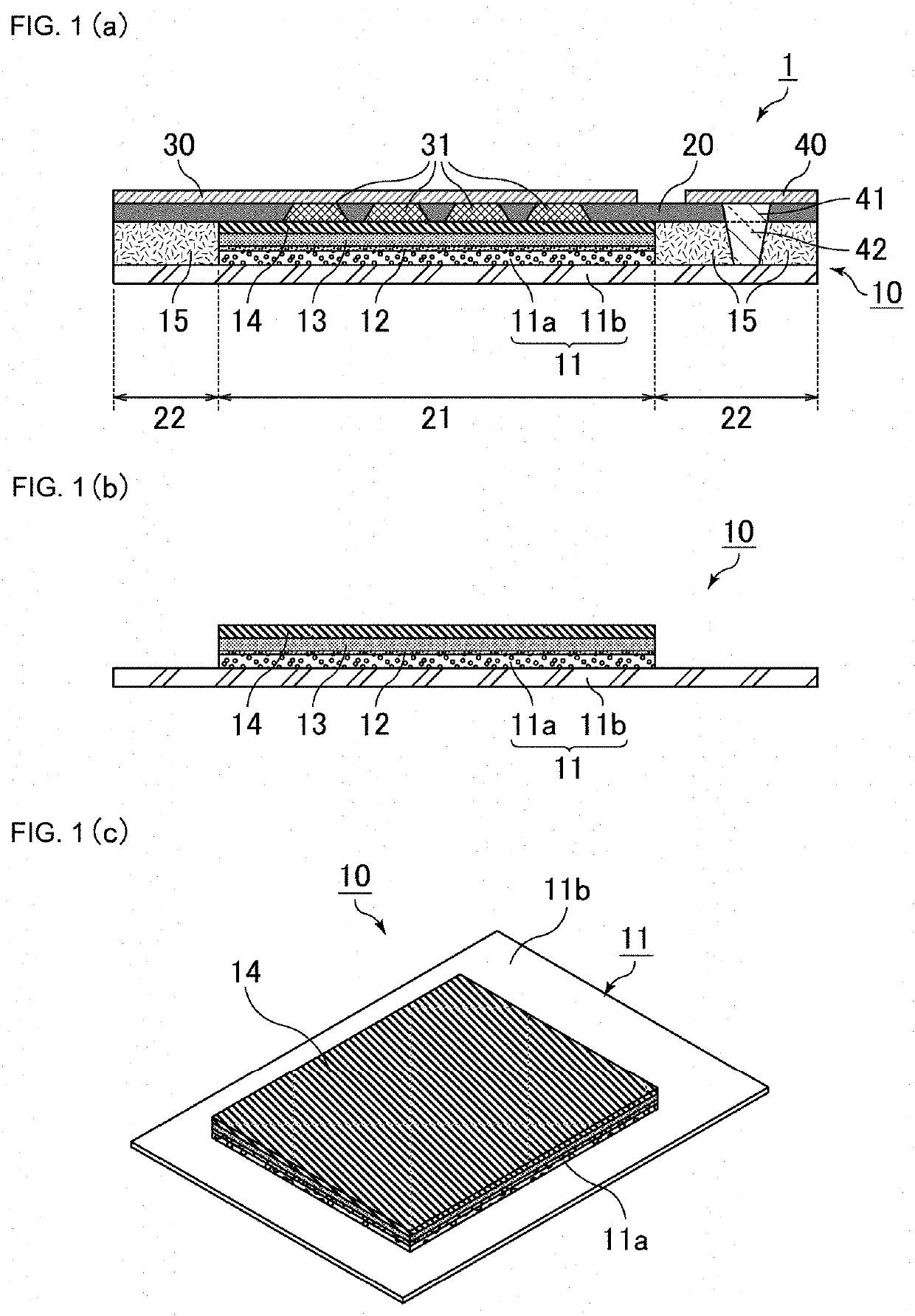
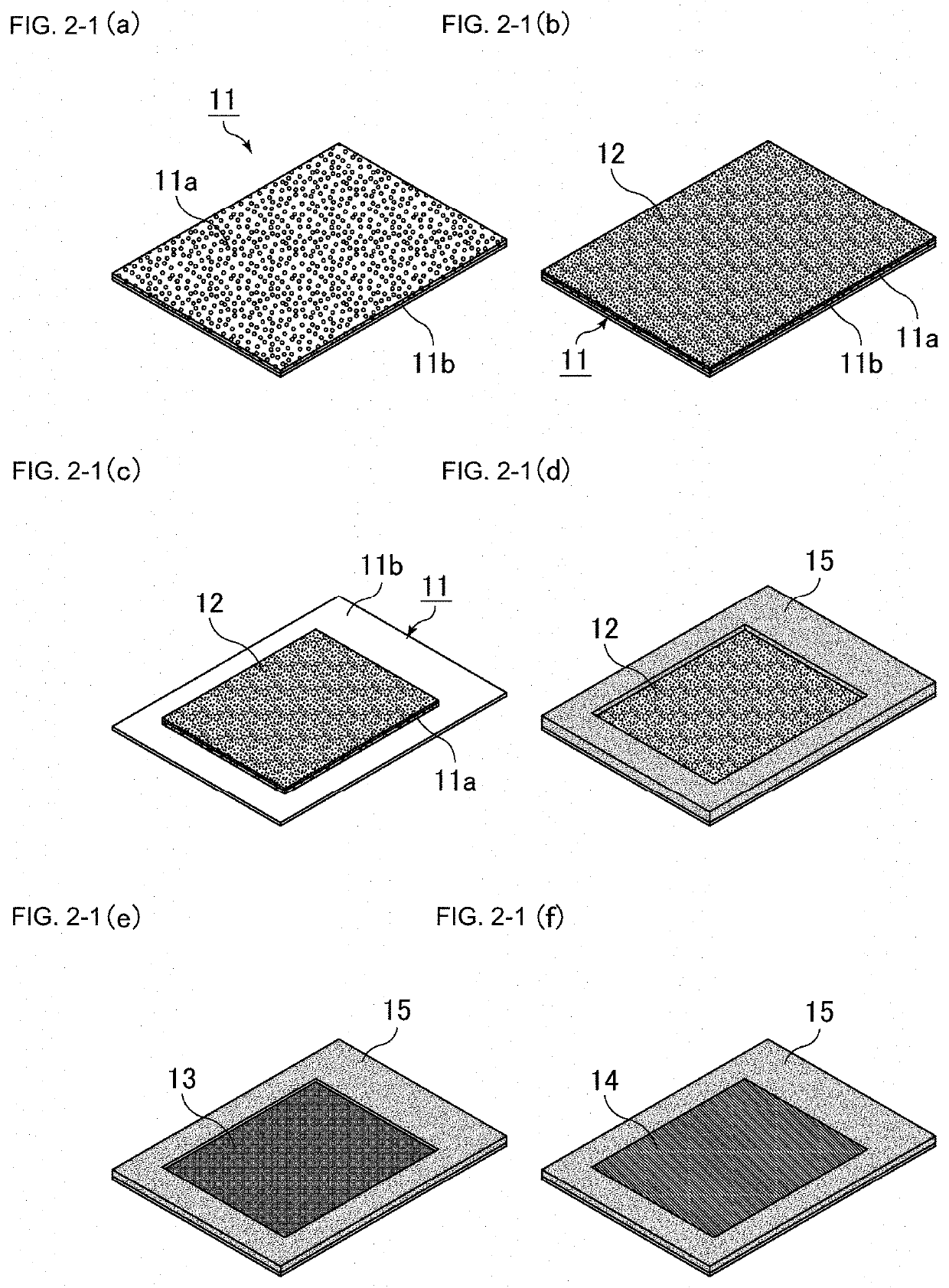
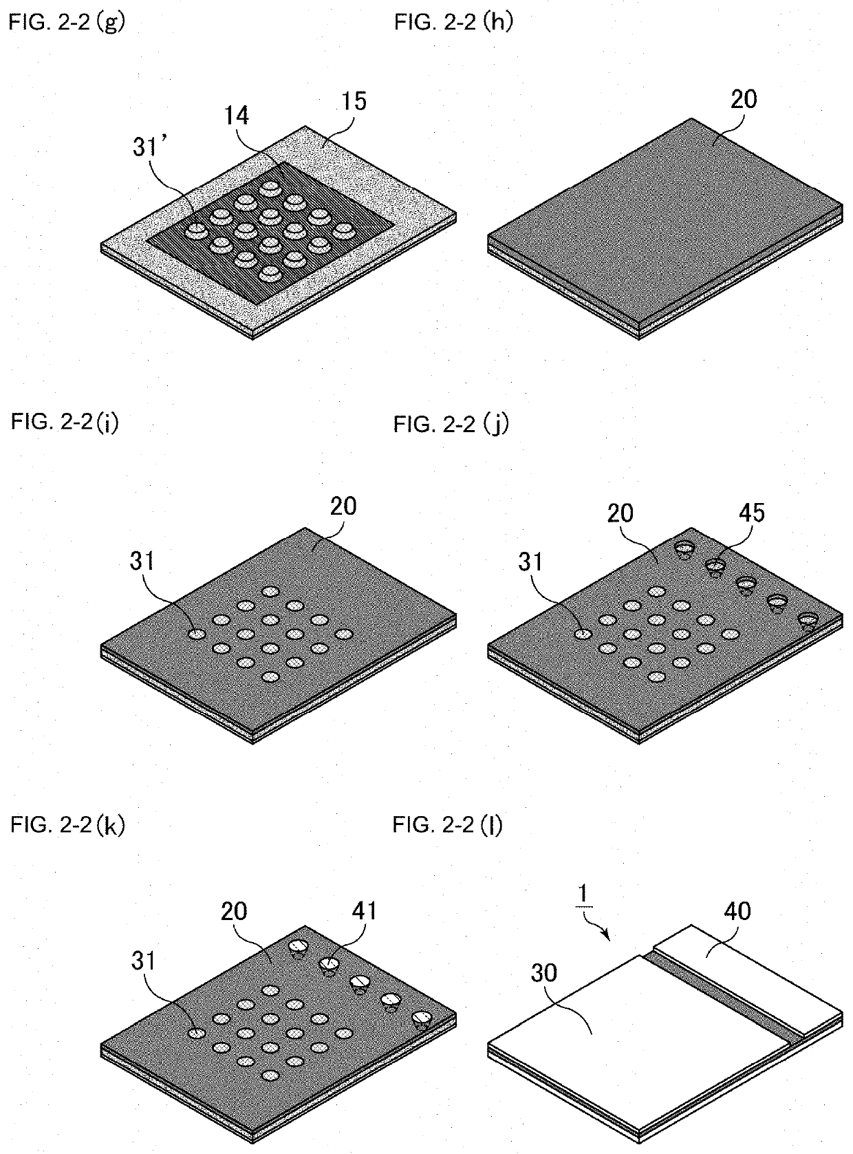
[0039]In the first embodiment of the present invention, an insulating layer is interposed between the core part and the sealing resin; the insulating layer, the sealing resin, and the anodic outer electrode are disposed on and above the core part in this order; a first anodic via electrode is formed in the sealing resin disposed on the insulating layer, and a second anodic via electrode is formed in the insulating layer disposed on the core part; and the core part is electrically drawn to the surface of the sealing resin through the first and second anodic via electrodes. One of the structural advantages of the first embodiment of the present invention is that the insulating layer, which comes into direct contact with the porous part, and the sealing resin may be composed of different materials. Since the surface of the cathode part which faces the principal surface of the capacitor element is covered with the sealing resin and the cathodic outer electrode and therefore has a substa...

second embodiment

[0084]In the second embodiment of the present invention, the sealing resin and the anodic outer electrode are disposed on and above the core part in this order; a first anodic via electrode is formed in the sealing resin disposed on the core part; the first anodic via electrode is arranged to come into direct contact with the core part; and the core part is electrically drawn to the surface of the sealing resin through the first anodic via electrode. In the structure according to the second embodiment of the present invention, the core part is arranged substantially close to the anodic outer electrode and the length of the via electrodes having a narrow conductive path may be relatively reduced accordingly. This makes it possible to reduce the overall resistance of the capacitor and pass a large current through the capacitor. In particular, in the case where a three-terminal capacitor is used as a circuit by-pass capacitor, the structure in which the proportion of the conductor in t...


PUM

PropertyMeasurementUnit
heightaaaaaaaaaa
heightaaaaaaaaaa
thicknessaaaaaaaaaa

Abstract

A solid electrolytic capacitor comprises a capacitor element including a valve-acting metal substrate including a core part and a porous part disposed on at least one principal surface of the core part, a dielectric layer formed on a surface of the porous part and a solid electrolyte layer is disposed on the dielectric layer. The capacitor element further includes a conductive layer disposed on the solid electrolyte layer. A sealing resin is located on the conductive layer and seals a principal surface of the capacitor element. A cathodic outer electrode is located on the sealing resin and is electrically connected to the conductive layer by a cathodic via electrode which extends through the sealing resin. An anodic outer electrode is electrically connected to the core part.

Description

CROSS REFERENCE TO RELATED APPLICATIONS[0001]The present application is a continuation of International application No. PCT / JP2017 / 030331, filed Aug. 24, 2017, which claims priority to Japanese Patent Application No. 2016-197928, filed Oct. 6, 2016, the entire contents of each of which are incorporated herein by reference.TECHNICAL FIELD[0002]The present invention relates to a solid electrolytic capacitor.BACKGROUND OF THE INVENTION[0003]Solid electrolytic capacitors typically include a capacitor element that includes a valve-acting metal substrate including a core part composed of a valve metal, such as aluminum, and a porous part formed in the surface of the core part, a dielectric layer formed in the surface of the porous part, a solid electrolyte layer disposed on the dielectric layer, and a conductive layer disposed on the solid electrolyte layer.[0004]Japanese Unexamined Patent Application Publication No. 2008-135427 (“Patent Document 1” 0) discloses a solid electrolytic capac...

Claims


Application Information

Patent Timeline
Patent Type & Authority Patents(United States)
IPC IPC(8): H01G9/025H01G9/012H01G9/04H01G9/00H01G9/15
CPCH01G9/025H01G9/0032H01G9/012H01G9/04H01G9/15H01G9/10
Inventor FURUKAWA, TAKESHI
Owner MURATA MFG CO LTD
Why Eureka
Try Eureka