Display

a thin, lightweight technology, applied in the field of thin, lightweight displays, can solve the problems of reducing contrast, over-high luminance of non-emitting states, unrecognizable screens, etc., and achieve the effect of small thickness and light weigh

Inactive Publication Date: 2006-09-05
SHARP KK
View PDF18 Cites 94 Cited by
  • Summary
  • Abstract
  • Description
  • Claims
  • Application Information

AI Technical Summary

Benefits of technology

[0015]The present invention, in view of the above problems, has an objective to achieve high visibility displays in both bright and dark environments on reflective types of displays without losing their features, small thickness and light weight, by utilizing ambient light and light emitted by an EL element.
[0016]Another objective is to provide a novel structure for emissive types of displays which utilizes ambient light for displays to cut down on energy consumption under intense ambient light by decreasing the emission from an emissive element, while retaining the overall luminance of the display element by increasing the contribution from the reflective liquid crystal.
[0022]The present invention hence offers novel, versatile types of displays, totally different from conventional ones, by making use of features of a circularly polarizing member and an EL element in combination with a reflective display element having a light-reflecting section. The invention also offers displays that show information in a clearly visible fashion, be it outdoors under clear skies or in a dark place, without giving up their thin, lightweight features. The invention also offers novel types of displays that allow a user to select one of various display modes at his / her own discretion according to surrounding conditions.
[0027]As detailed above, the invention realizes displays capable of making use of both ambient light and light emitted by an EL element to present information in a clearly visible fashion in both bright and dark environments, owing to a combined structure of an EL element and a reflective display element (for example, electrophoresis display element) which are independently controllable in terms of display operations, without giving up the thin, lightweight features of reflective displays.

Problems solved by technology

The structure entails a problem termed “washout” where intense ambient light in comparison to the light produced by the device, having entered the transparent substrate 2 and been reflected from the cathode 7, produces exceedingly high luminance for a non-emitting state, i.e., black state, reducing contrast greatly and making the screen unrecognizable.
The important issue here is to find how to reduce reflected ambient light.
Although only a small amount of energy is needed to modulate the transmittance of a liquid crystal element, the backlight must be continuously powered on no matter what is being displayed; the non-emissive liquid crystal display overall requires large power for its operation.
Transmissive color liquid crystal displays are also highly power-consuming, since the backlight emits light in an increased amount to address the problem of low visibility of the display under intense ambient light by boosting the otherwise relatively moderate luminance.
The problem becomes more evident when color is implemented by the use of a color filter, which absorbs light and further reduces the luminance of the screen.
However, the technique is not a result of constructive use of ambient light in display operations: the EL element emits non-polarized light due to the presence of the circularly polarizing plate with about 50% of the light absorbed by that polarizing plate.
The structure forms a mirror-like surface and cannot produce a bright white screen with wide viewing angles.
Besides, the structure in which the transparent organic EL element is placed in front of the reflective liquid crystal display element allows reflection of ambient light, causing display quality to fall far below satisfactory level.
The touch panel, stacked on the display for use, which is disclosed in the application, reflects ambient light and degrades visibility: the unwelcome properties manifest themselves clearly in reflective liquid crystal displays.
They, however, mentioned nothing about an optimum device structure to make use of the material.

Method used


Image

  • Display
  • Display
  • Display

Examples


embodiment 1

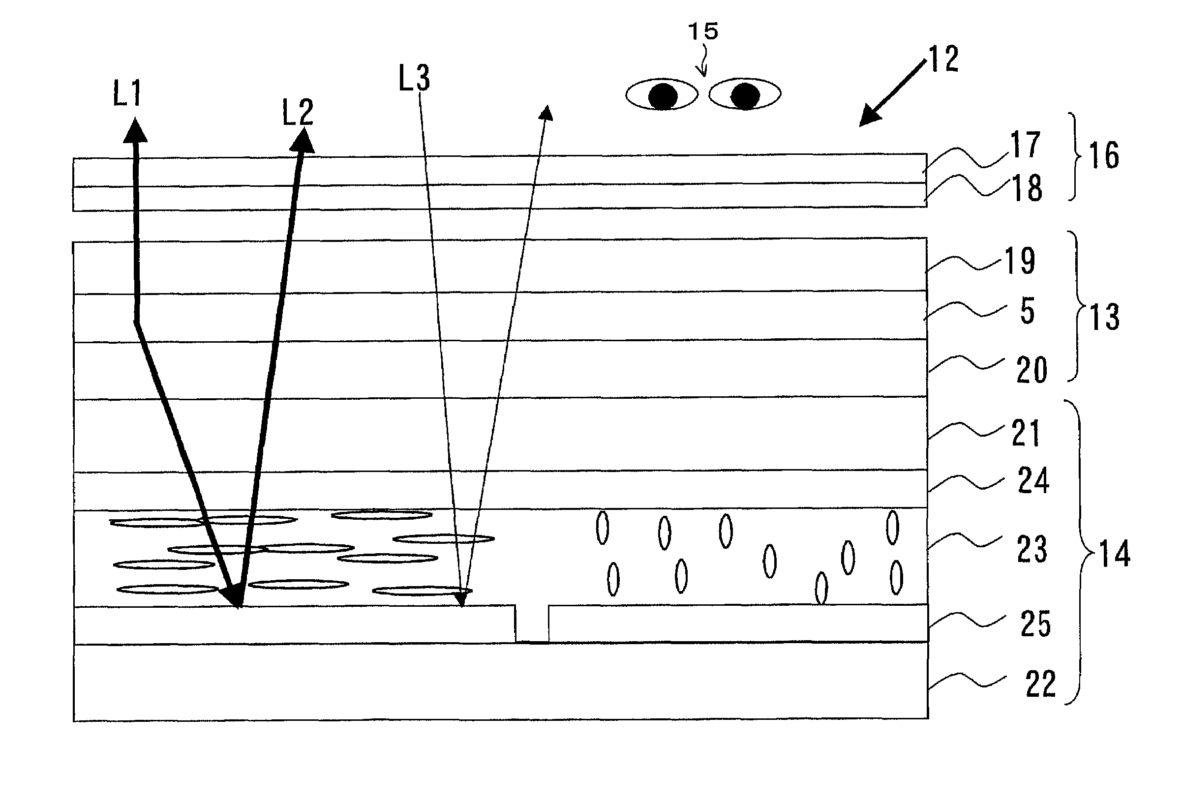
[0059]FIG. 1 is a schematic cross-sectional view of the structure of a display 12, a first embodiment in accordance with the present invention. There is provided a reflective display element 14 integrally on the back of a transmissive EL element 13 and a circularly polarizing means 16 on the side thereof facing an observer 15. These two elements and the observer are located opposite to one another.

[0060]It is presumed here that the elements 13, 14 are driven by simple matrix addressing scheme; they may be however driven by active matrix addressing scheme. The EL element is an organic type, the reflective display element is a reflective type containing liquid crystal, and the circularly polarizing means has a layered structure including a polarizing plate 17 and a quarter-wave plate 18; however these are mere examples and by no means intended to restrict the scope of the invention.

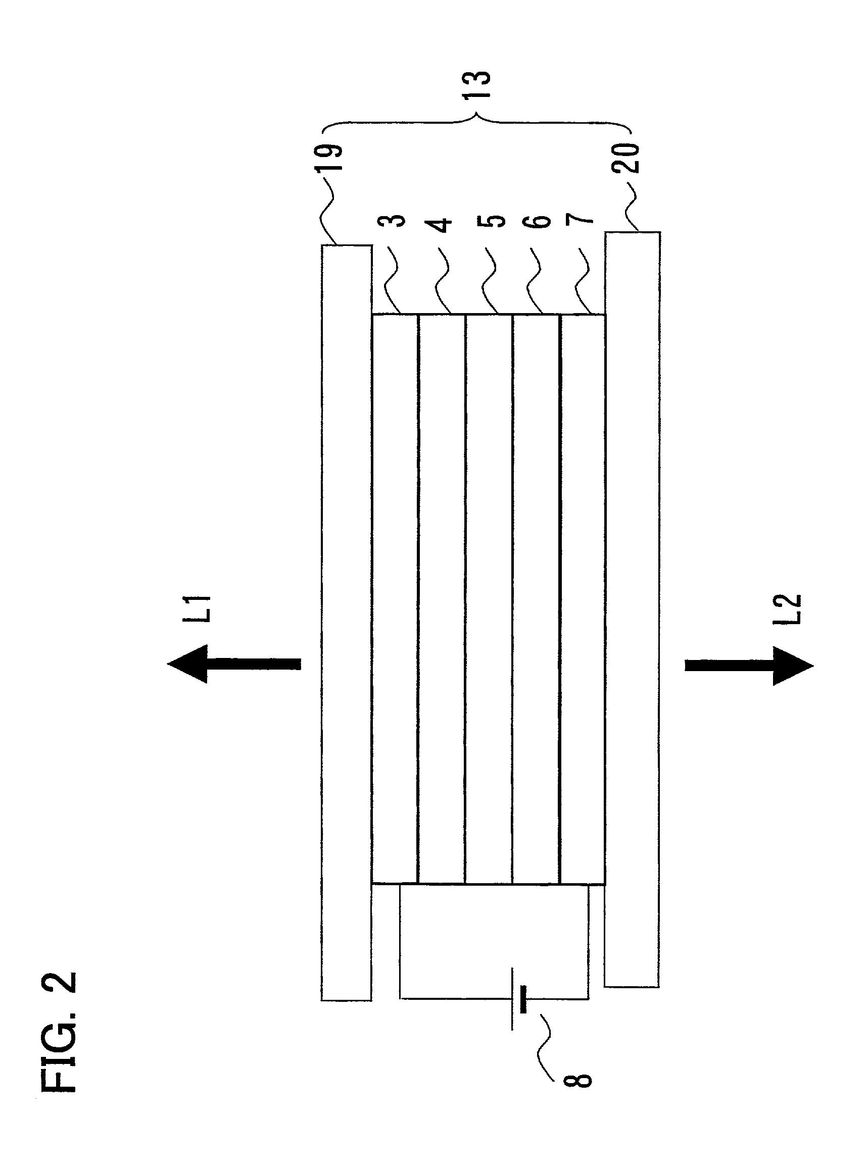
[0061]The EL element 13 has a light-emitting layer 5 formed on a transparent substrate 19 and is covered...

embodiment 2

[0083]FIG. 9 shows another display in accordance with the present invention having a structure which is capable of displaying full colors when the EL element 32 is powered on, owing to the formation of RGB light emission patterns in the light-emitting layer 31 in the EL element 32. There is no change in the rest of the basic structure from embodiment 1.

[0084]The light-emitting layer 31 is formed, as an example, as follows: fabricate a body composed of a red-light-emitting organic layer and an electrode stacked thereon by vacuum vapor deposition. Move the mask parallel and stack a green-light-emitting organic layer on the electrode by vacuum vapor deposition. Finally, move the mask further parallel and stack a blue light-emitting organic layer on the electrode.

[0085]A concrete example is now given of the formation method of the light-emitting layer 31. The organic layer providing green light emission is formed by vapor-depositing, as a hole transfer layer, N,N -diphenyl-N,N′-bis(3-me...

embodiment 3

[0089]FIG. 10 shows another display in accordance with the present invention having a structure, enabling full color displays in either of the aforementioned display schemes, in which RGB light-emitting patterns are formed in the light-emitting layer 31 in the EL element 32 and a color filter layer 35 is formed on the transparent substrate 21 in the reflective display element 34. There is no change in the rest of the basic structure from embodiment 2.

[0090]In the figure, the display 33 has an almost identical structure to that of the display 30 of embodiment 2, but is characterized by the formation on the glass substrate 21 of a color filter layer 35 of a colorant dispersion scheme which is transparent to red, green, and blue light. The color filter layer 35 includes red, green, and blue-colored filters, arranged in stripes, which correspond to individual pixels in a single picture element. On the top of the color filter layer35 is there provided a flattening film 36 and a transpare...


PUM

PropertyMeasurementUnit
transmittanceaaaaaaaaaa
thicknessaaaaaaaaaa
transmittanceaaaaaaaaaa

Abstract

A display includes a polarizing member and a reflective display element behind an EL element. The EL element self-emits light to display information and doubles as a display-use light source for the reflective display element. In a sufficiently bright environment, ambient light enters a liquid crystal layer after passing through a frontal substrate of the reflective display element, and is reflected from a metal electrode to produce displays. In addition to the direct light from the EL element, light that enters the liquid crystal layer is simultaneously used. In a dark environment, the EL element emits light, and displayed contents are visible owing to the reflection from the metal electrode as well as directly exiting light. The structure makes it possible to provide a novel type of display that allows a user to select one of various display modes at his / her own discretion according to surrounding conditions and that also shows information in a clearly visible fashion, be it outdoors under clear skies or in a dark place, without giving up their thin, lightweight features.

Description

FIELD OF THE INVENTION[0001]The present invention relates to thin, lightweight displays incorporated in various word processors, laptop personal computers, and other IT devices, video displays and game machines, portable VTRs, digital cameras, etc., especially those intended for use both indoors and outdoors and in vehicles, aircraft, vessels, and other environments in which illumination conditions change rapidly and harshly.BACKGROUND OF THE INVENTION[0002]Displays capable of electrically rewriting a screen are classified as emissive types that emit light by themselves and non-emissive types that use ambient light for illumination. Thin, lightweight emissive displays include electroluminescence (EL) elements and plasma display panels (PDPs) and non-emissive counterparts include liquid crystal displays. These displays are already available for commercial use.[0003]The liquid crystal display have low contrast, narrow viewing angles, and other shortcomings. A lot of research efforts a...

Claims


Application Information

Patent Timeline
Patent Type & Authority Patents(United States)
IPC IPC(8): G02F1/13G02B5/20G02B5/30G02B5/32G02B27/28G02F1/1335G02F1/13357G02F1/13363G02F1/1362G02F1/139G02F1/167G09F9/30G09F9/35H01L27/32H01L51/50H05B33/02H05B33/14
CPCG02F1/133603G02F1/133621H01L51/5281G02F2001/133616G02F2203/02G02F1/1397G02F1/133616H10K50/86
Inventor MITSUI, SEIICHIKABE, MASAAKISAKO, TEIYUUCHIDA, HIDEKI
Owner SHARP KK
Why Eureka
Try Eureka