Shift-type multi-phase-shifter drive transmission device

a transmission device and multi-phase technology, applied in mechanical equipment, transportation and packaging, gearing, etc., can solve the problems of unfavorable engineering and aesthetics, high cost, complicated structure, etc., and achieve the effect of reducing the amount of drive sources, simple structure and effective cost reduction

Active Publication Date: 2021-06-01
KUNSHAN ENDIAN COMM EQUIP CO LTD
View PDF4 Cites 1 Cited by
  • Summary
  • Abstract
  • Description
  • Claims
  • Application Information

AI Technical Summary

Benefits of technology

[0006]In view of shortcomings of the prior art described above, an object of the present invention is to provide a shift-type drive transmission device which has a simple structure and adopts a drive source to drive multiple phase shifters.
[0022]As mentioned above, the shift-type multi-phase-shifter drive transmission device provided by the present invention has beneficial effects as follows. The shift-type drive transmission device comprises a shifting mechanism and multiple angle adjustment mechanisms all of which are set on a stand. When the shift-type drive transmission device works, the drive device firstly drives the shifting rack of the shifting mechanism to move to a position which is corresponding to one of the angle adjustment mechanisms, the shifting bulge on the shifting rack is against the driving lever for engaging the active clutch gear with the passive clutch gear of the corresponding angle adjustment mechanism, so that the drive device is able to drive the active clutch gear and the passive clutch gear through a transmission mechanism to rotate, so as to further drive a transmission screw, thus a transmission nut on the transmission screw implements the reciprocating linear motion. The shift-type drive transmission device is able to drive multiple phase shifters through one drive device to perform angle adjustment, which reduces an amount of the drive sources and effectively decreases cost; and meanwhile, the shift-type drive transmission device has simple structure, is able to be modularly assembled, is more convenient to be repaired and replaced, and its appearance is more beautiful. There is no problem of stringing and the performance is more reliable. Moreover, in this way, the ruler can be adjusted manually, and the operation is simpler and more convenient.

Problems solved by technology

These transmission methods have following problems.
Firstly, the multi-frequency electrically adjusted antenna requires multiple motor drive sources, and the cost is high.
If the motor drive sources are separately placed inside the antenna with control boards thereof, then they cannot be quickly repaired and replaced; and moreover, the internal power supply lines need to be connected in series, and the structure is complicated.
If the motor drive sources are separately plugged and unplugged with control boards thereof, the power supply lines need to be connected in series outside the antenna, which is unfavorable for engineering and aesthetics.
If a single motor drive source is placed separately and the control panel thereof is placed inside the antenna, rapid repair and replacement cannot be achieved, and the power supply lines need to be connected in series.
If a single motor drive source is used separately and the control board assembly is plugged and unplugged, the drive source cannot be quickly repaired or replaced, and the internal power supply lines need to be connected in series.
Moreover, the above methods cannot realize manual driving, and the design of the angle adjustment ruler is also difficult.

Method used


Image

  • Shift-type multi-phase-shifter drive transmission device
  • Shift-type multi-phase-shifter drive transmission device
  • Shift-type multi-phase-shifter drive transmission device

Examples


Embodiment Construction

[0028]The present invention is described as below by way of specific embodiments, and those skilled in the art can readily understand other advantages and functions of the present invention from the disclosure.

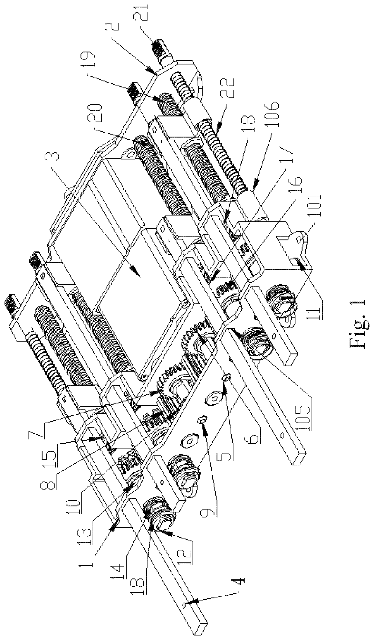
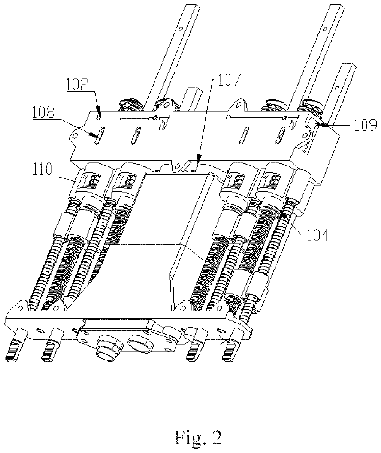
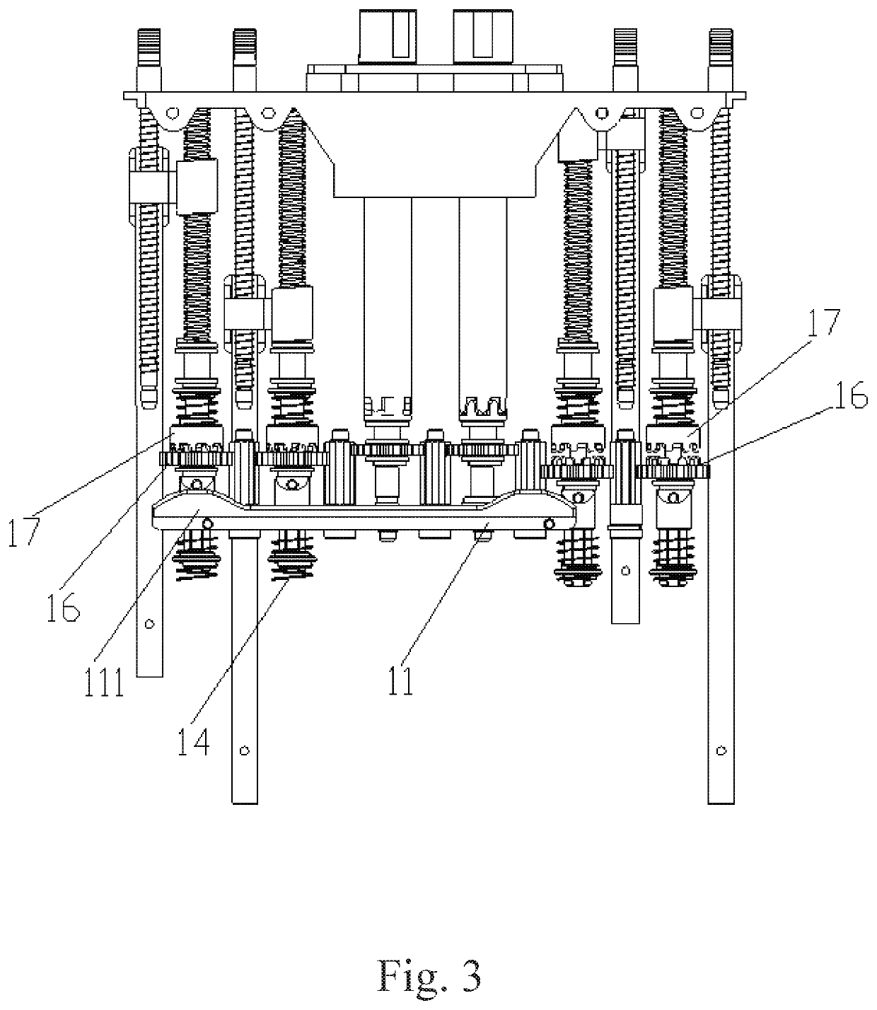
[0029]Referring to FIGS. 1 to 4, it should be understood that the structures, the proportions, the sizes, and the like, which are illustrated in the drawings of the present specification, are only used to clarify the contents disclosed in the specification for being understood and read by those skilled in the art, and are not intended to limit the implementation of the present invention. Therefore, they have no technical significance. Any modification of the structure, change of the proportional relationship or adjustment of the size should fall within the scope of the technical content disclosed by the present invention without affecting the effects and the achievable objectives of the present invention. Meanwhile, the terms “upper”, “lower”, “left”, “right”, “intermediate” a...


PUM


Abstract

A shift-type multi-phase-shifter drive transmission device includes a drive device (3), a shifting mechanism, multiple angle adjustment mechanisms and multiple ruler mechanisms. When the shift-type drive transmission device works, the drive device (3) firstly drives a shifting rack (11) of the shifting mechanism to move to a position which is corresponding to one of the angle adjustment mechanisms, a shifting bulge (111) on the shifting rack (11) is against a driving lever (13) for engaging an active clutch gear (16) with a passive clutch gear (17) of the corresponding angle adjustment mechanism, so as to further drive a transmission screw (19), thus a transmission nut (20) on the transmission screw (19) implements the reciprocating linear motion. The shift-type drive transmission device is able to drive multiple phase shifters through one drive device (3) to perform angle adjustment, which reduces an amount of the drive sources and effectively decreases cost.

Description

CROSS REFERENCE OF RELATED APPLICATION[0001]This is a U.S. National Stage under 35 U.S.C 371 of the International Application PCT / CN2018 / 073731, filed Jan. 23, 2018, which claims priority under 35 U.S.C. 119(a-d) to CN 201710059712.4, filed Jan. 24, 2017.BACKGROUND OF THE PRESENT INVENTIONField of Invention[0002]The present invention relates to the field of base station electrically adjusted antenna phase shifter technology, and more particularly to a shift-type drive transmission device for phase shifters.Description of Related Arts[0003]The base station electrically adjusted antenna system plays an important role in the mobile communication network. As a key component to realize the antenna electrically adjusted function, the phase shifter is the key research object of the electrically adjusted antenna. The phase shifter mainly uses a manual or electrical device as a drive source, and then uses a transmission mechanism to realize the phase shifting action, thereby achieving phase ...

Claims


Application Information

Patent Timeline
Patent Type & Authority Patents(United States)
IPC IPC(8): F16H63/30F16H37/02
CPCF16H63/30F16H37/02F16H2200/2002F16H37/12F16H25/2204H01Q3/32H01P1/18
Inventor FU, XIANGYA
Owner KUNSHAN ENDIAN COMM EQUIP CO LTD
Why Eureka
Try Eureka