Self-contained power signal generation system for electricity meter testing

a self-contained power signal and electricity meter technology, which is applied in the direction of electrical apparatus casings/cabinets/drawers, safety/protection circuits, instruments, etc., can solve the problems of hindering the testing stability and accuracy, affecting the test signal, so as to reduce the size and weight of the load box, reduce electronic noise, and increase the accuracy and stability of the test signal.

Active Publication Date: 2021-06-15
TECH FOR ENERGY CORP
View PDF6 Cites 1 Cited by
  • Summary
  • Abstract
  • Description
  • Claims
  • Application Information

AI Technical Summary

Benefits of technology

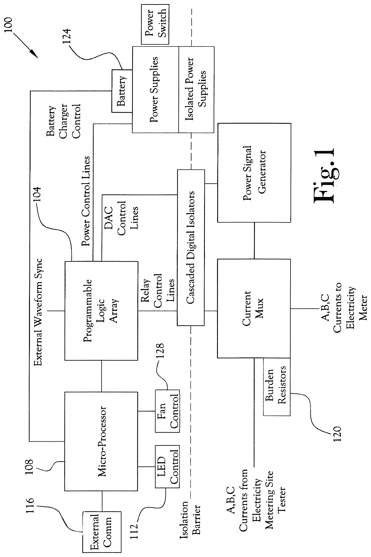
[0005]The present general inventive concept provides various embodiments of an electricity meter load box and system that includes features such as being battery-operated so as to remove the need for an external AC power source; using differential signals to reduce electronic noise and increase accuracy and stability of the test signal; using high-frequency switching to reduce the size and weight of the load box; and using signal isolation to improve accuracy of the test, protect equipment and personnel, and provide proper function.

Problems solved by technology

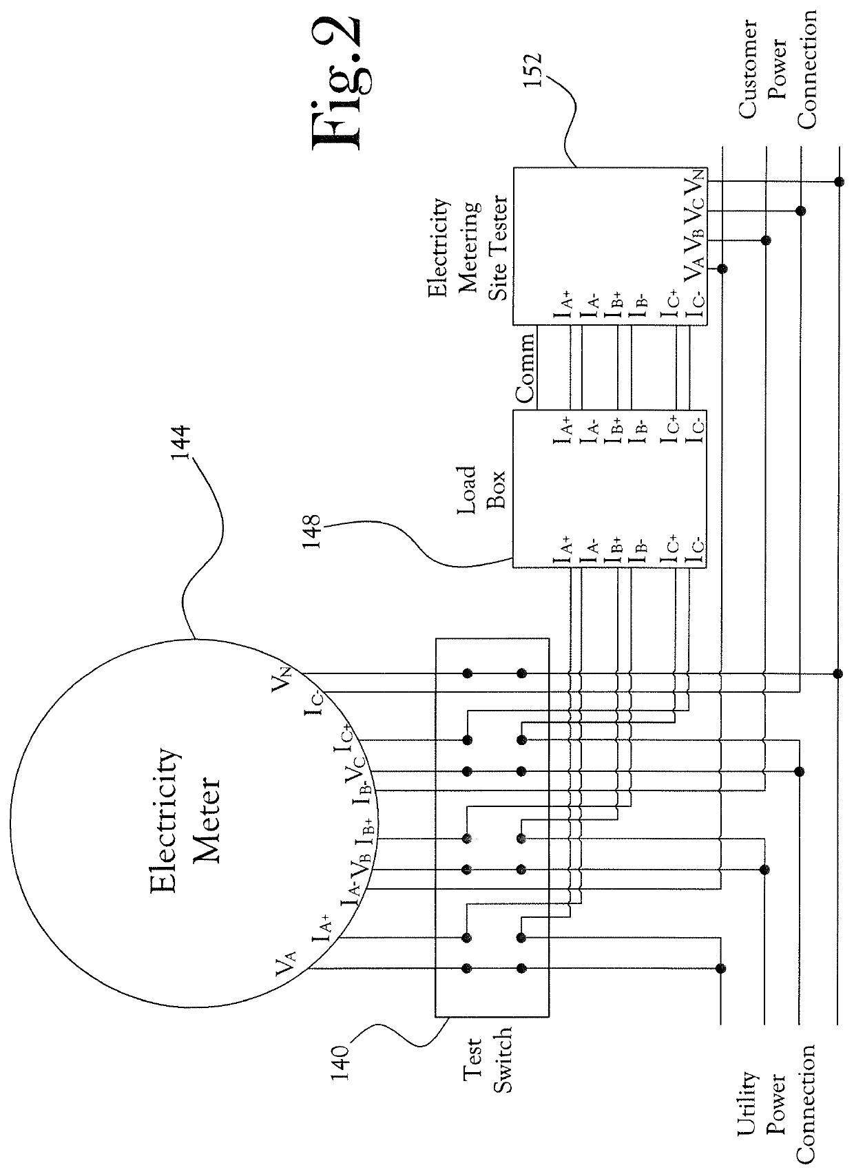
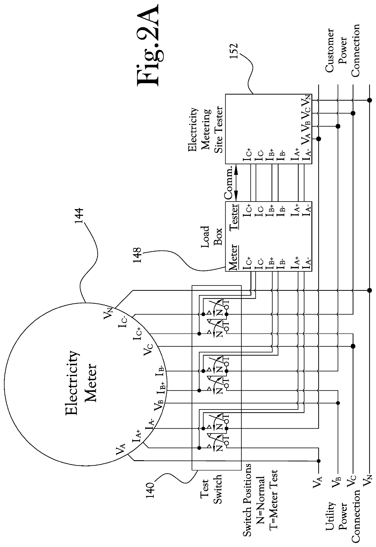
Challenges arise in meter testing when the relevant test signal is not readily available in the field and when the relevant test signal is associated with a high voltage environment.
Test sites can also be subject to large amounts of electromagnetic noise, hindering testing stability and accuracy.
Moreover, conventional load boxes are typically rather large and heavy, making it difficult for a technician to easily carry and transport the load box to a particular testing site.

Method used


Image

  • Self-contained power signal generation system for electricity meter testing
  • Self-contained power signal generation system for electricity meter testing
  • Self-contained power signal generation system for electricity meter testing

Examples


Embodiment Construction

[0018]Reference will now be made to the example embodiments of the present general inventive concept, examples of which are illustrated in the accompanying drawings and illustrations. The example embodiments are described herein in order to explain the present general inventive concept by referring to the figures.

[0019]The following detailed description is provided to assist the reader in gaining a comprehensive understanding of the structures and fabrication techniques described herein. Accordingly, various changes, modification, and equivalents of the structures and fabrication techniques described herein will be suggested to those of ordinary skill in the art. The progression of fabrication operations described are merely examples, however, and the sequence type of operations is not limited to that set forth herein and may be changed as is known in the art, with the exception of operations necessarily occurring in a certain order. Also, description of well-known functions and con...


PUM


Abstract

The present general inventive concept is directed to a signal generation system, device, and method for meter testing, including a digital signal generator to generate an arbitrary digital test signal, a digital-to-analog converter to convert the arbitrary digital test signal to an analog test signal, a signal converter to convert the analog test signal to a differential pair of signals corresponding to the analog test signal, and a power signal generator including: an input module to receive the differential pair of signals; an amplifier to amplify the differential pair of test signals; and an output module to output an output differential pair of signals to a load, to feed back a proportional representation of the output differential pair of signals to the input module, and to receive the amplified differential pair of signals from the amplifier.

Description

CROSS-REFERENCE TO RELATED APPLICATIONS[0001]This application claims the benefit of U.S. Provisional Patent Application Ser. No. 62 / 565,796, filed on Sep. 29, 2017, the contents of which are incorporated herein by reference in its entirety.FIELD OF INVENTION[0002]The present general inventive concept relates to a system for testing electricity meters, and, more particularly, to a portable, battery operated capable load box for testing electricity meters and other auxiliary portions of installation sites.BACKGROUND[0003]Electricity meters are well known to measure electrical power consumption. Electricity meters should be tested to ensure the meters are measuring power accurately. Electricity meters can be tested using a load box to input a desired test signal into the meter, and then measure the performance of the meter to verify that the meter is performing properly. Challenges arise in meter testing when the relevant test signal is not readily available in the field and when the r...

Claims


Application Information

Patent Timeline
Patent Type & Authority Patents(United States)
IPC IPC(8): G01R22/06H02J7/00H03F3/45H05K7/14H05K7/20H05K5/00H03M1/66
CPCH02J7/0068G01R22/068H02J7/0029H03F3/45475H05K5/0086H05K7/1427H05K7/20136H05K7/20209H03F2200/129H03F2203/45116H03M1/66H03F2203/45138H03F2200/408G01R35/04G01R11/25H03F1/02H03F3/21H03F3/45
Inventor OMOUMI, KEVIN CHRISTOPHERBLALOCK, ALLEN VAUGHNBOUSE, KAIHUDSON, ROBERT STEPHEN
Owner TECH FOR ENERGY CORP
Why Eureka
Try Eureka