
Functional membrane for ion beam transmission, beam line device and filter device each having the same, and method of adjusting filter device

a filter device and ion beam technology, applied in the direction of accelerators, particle separator tubes, electric discharge tubes, etc., can solve the problems of increased gas leakage to the beam line, difficult to achieve the maintenance of the function of a stripper using gas and the maintenance of high vacuum of the beam line, and no longer improve the emittance. , to achieve the effect of improving the transmittance and improving the emittan

Active Publication Date: 2021-06-29
JAPAN ATOMIC ENERGY AGENCY INDEPENDANT ADMINISTRATIVE CORP +1
View PDF35 Cites 0 Cited by
  • Summary
  • Abstract
  • Description
  • Claims
  • Application Information

AI Technical Summary

Benefits of technology

The present invention is about a beam line device that uses a functional membrane for ion beam transmission. The invention improves the transmission of the ion beam by adjusting the crystal plane in the membrane to be parallel to the beam's direction of travel. This results in higher beam brightness and better ion emission.

Problems solved by technology

However, even when the beam converging lens is used, emittance that has once been deteriorated can be no longer improved (Non-Patent Document 1).
A main factor restricting the miniaturization of an AMS device is that it is difficult to achieve both the maintenance of the function of a stripper using gas and the maintenance of high vacuum of a beam line.
When the amount of gas injected into the stripper is increased so as to maintain the function of the gas stripper, gas leakage to the beam line is increased.
Thus, ions collide with leaking gas particles to be scattered, which may result in high probability of deviation of the trajectory thereof.
At present, the miniaturization of the AMS device is restricted due to trade-off between the maintenance of the function of the stripper and the maintenance of high vacuum of the beam line.
Thus, development of the FMIT having improved ion beam transmittance may lead to drastic miniaturization of the AMS device.

Method used


Image

  • Functional membrane for ion beam transmission, beam line device and filter device each having the same, and method of adjusting filter device
  • Functional membrane for ion beam transmission, beam line device and filter device each having the same, and method of adjusting filter device
  • Functional membrane for ion beam transmission, beam line device and filter device each having the same, and method of adjusting filter device

Examples


example 1

[0110]An example creating the ICT state is illustrated in FIG. 9. In the present example, an experimental system on the left side of the drawing was used to make 7.0 MeV 10B2+ pass through a pinhole and enter a Si crystal membrane. The yield of ions transmitted through the crystal membrane in the gas ionization chamber was measured in each of the ICT and IRT states while the ions were sorted by an electrostatic deflector, and a charge state distribution was calculated from the measurement result. The thickness (200 nm) of the Si crystal membrane satisfies the standards of the thickness shown in Table 1, and thus the function of the functional membrane for ion beam transmission according to the present invention is guaranteed to be achieved. Actually, the average charge number calculated from FIG. 9 is about 4.0 which is equal to the literature value. That is, the charge state distribution reaches equilibrium, which proves that the function of the functional membrane for ion beam tra...

example 2

[0111]An example in which the present invention is applied to the degrader 50 for AMS is illustrated in FIG. 10. As described above, in the AMS, when there exist stable isobars having a mass equal to the mass of the AMS nuclides (10B for 10Be, 36S for 36CI, 53Cr for 53Mn, etc.), they become nuclides (interference nuclides) interfering with measurement of the AMS nuclides, and separation of these interference nuclides from the AMS nuclides is the main technological issue.

[0112]The degrader 50 is used in the following manner as one separation technique. When both the AMS nuclides and interference nuclides are made to enter the membrane, the energy of one of the AMS nuclides and interference nuclides is lost comparatively significantly, because of the atomic number dependency of stopping power, with the result that energy difference occurs between them. Thus, the AMS nuclides and interference nuclides are separated based on the difference by an energy analyzer provided at the rear stag...


PUM


Abstract

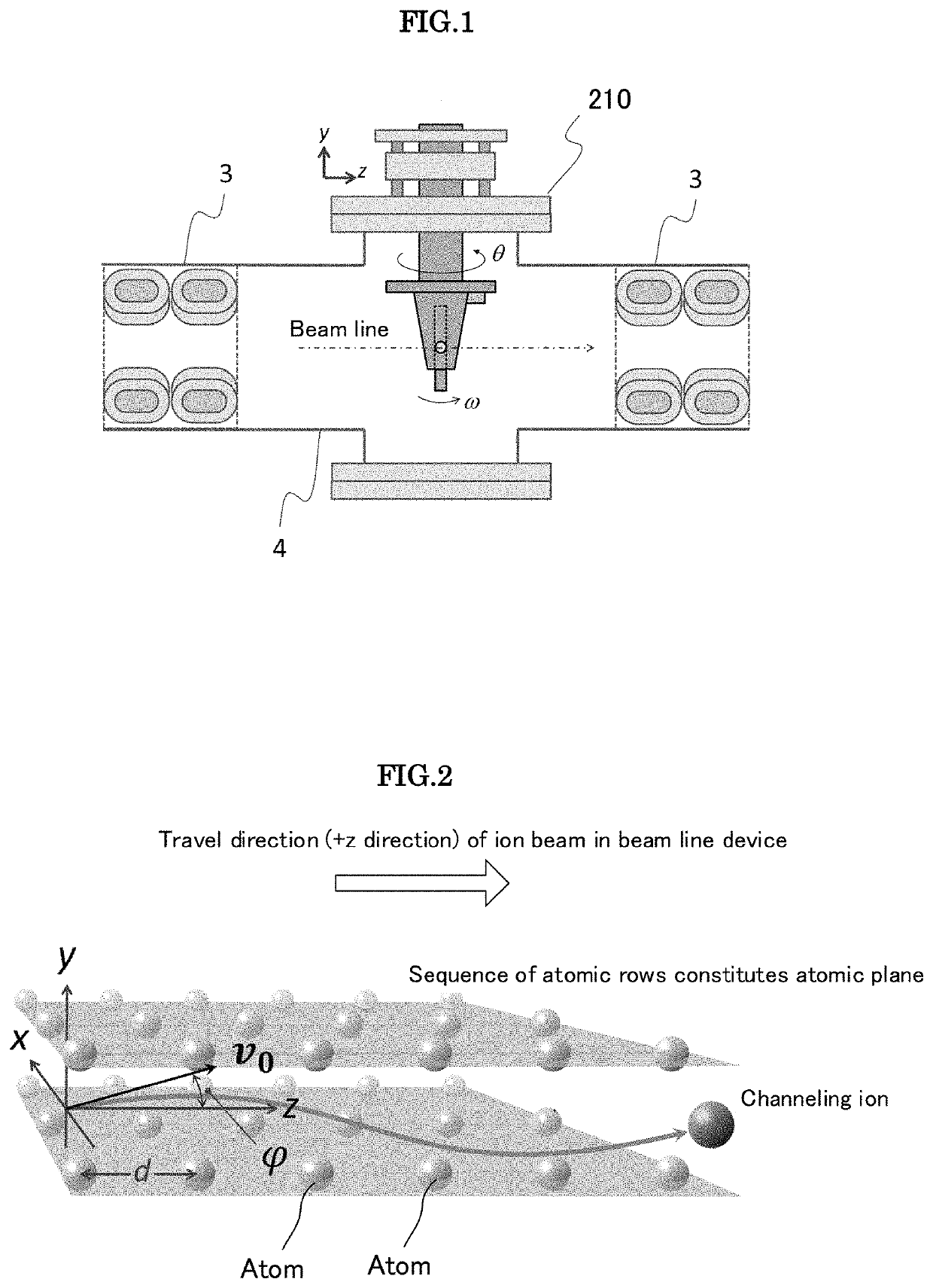
To provide a functional membrane for ion beam transmission capable of enhancing ion beam transmittance and improving beam emittance. A functional membrane for ion beam transmission according to the present invention is used in a beam line device through which an ion beam traveling in one direction passes and has a channel. The axis of the channel is substantially parallel to the travel direction of the ion beam.

Description

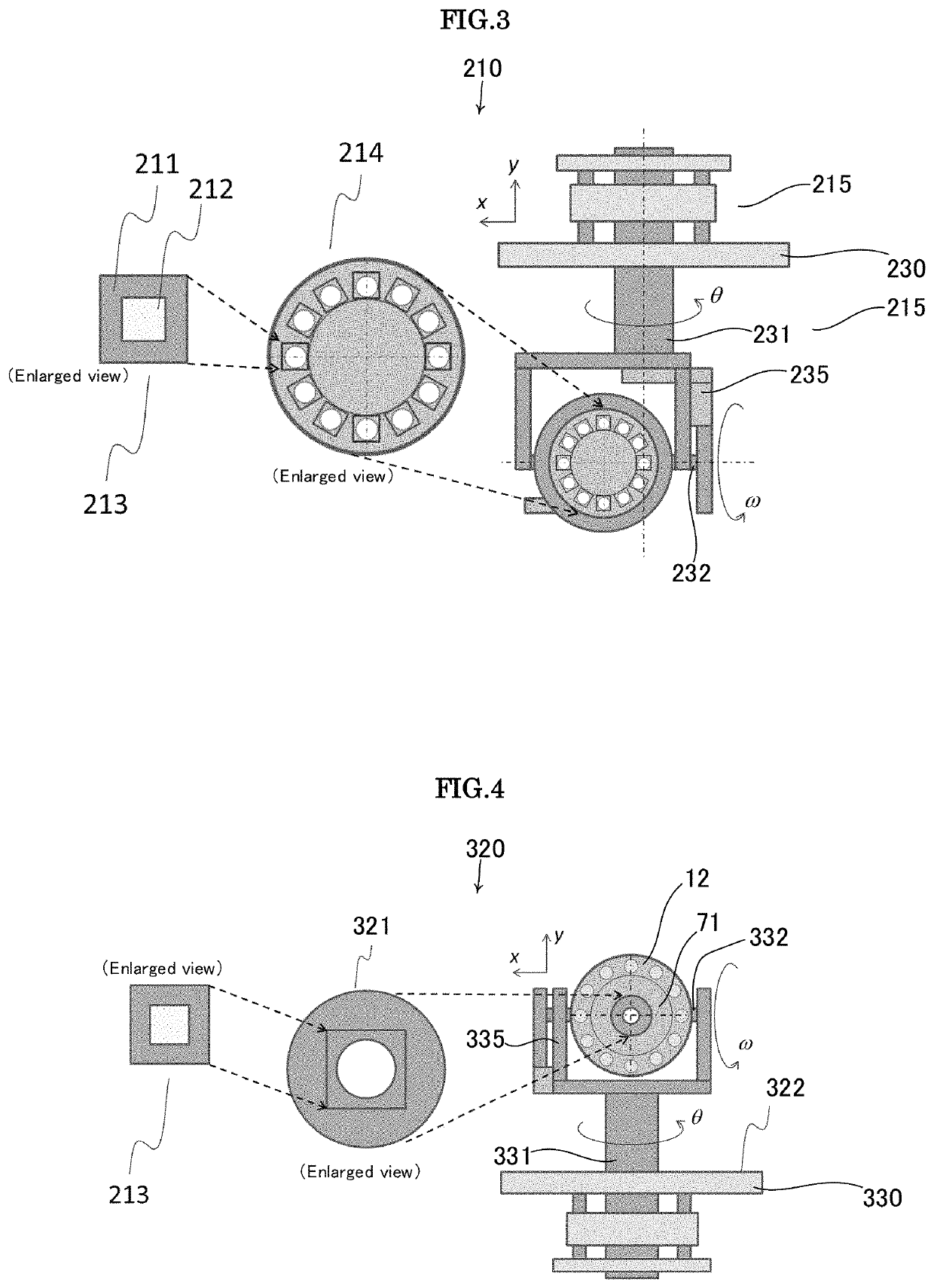
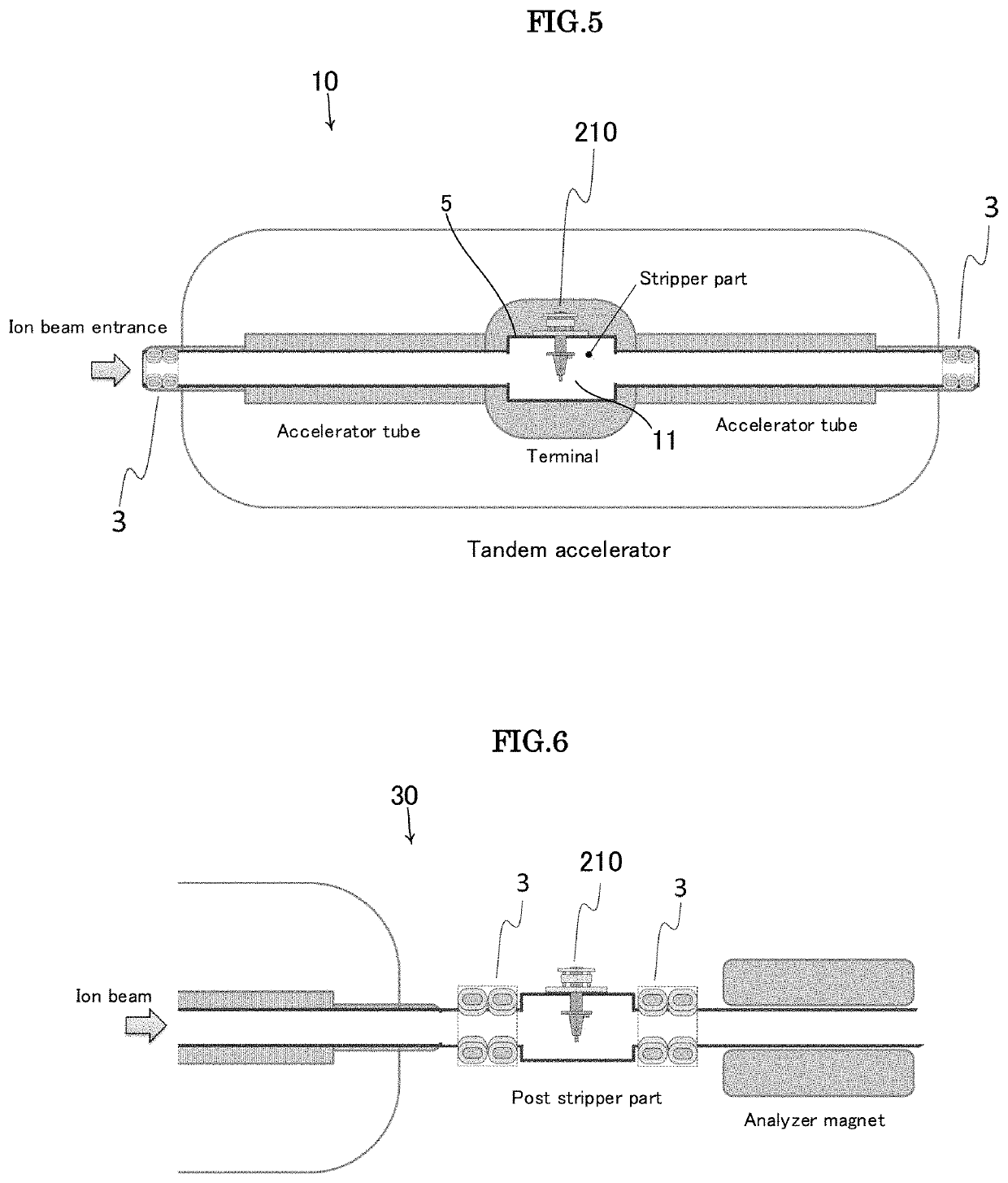
TECHNICAL FIELD[0001]The present invention relates to a functional membrane for ion beam transmission for improving ion beam transmittance, a beam line device using the functional membrane for ion beam transmission, and a method of adjusting the functional membrane for ion beam transmission.BACKGROUND ART[0002]Generally, in a device such as an accelerator, an ion beam having an energy of about 1 MeV (several 10 keV) or more can be transmitted through a membrane having a thickness of 1 μm (several 10 nm). Conventional functional membranes for ion beam transmission (hereinafter, referred to also as “FMIT”) utilize the transmission phenomenon as a basis.[0003]Examples of the application of the FMIT include a stripper for a tandem accelerator having a charge conversion function, a post stripper having a function of increasing the number of charges in a beam line, and a degrader having an energy attenuation function. The stripper and post stripper are also referred to simply as “stripper...

Claims


Application Information

Patent Timeline
Patent Type & Authority Patents(United States)
IPC IPC(8): H01J37/09H05H5/06H05H5/02H01J37/08
CPCH05H5/02H01J37/08H01J37/09H05H5/063G21K1/14H01J37/04H01J2237/004H05H7/00H05H7/12H05H2007/005H05H2007/125H01J49/00
Inventor FUJITA, NATSUKOMATSUBARA, AKIHIRO
Owner JAPAN ATOMIC ENERGY AGENCY INDEPENDANT ADMINISTRATIVE CORP
Learn More