Bolt grease removal device

a grease removal device and bolt technology, applied in the direction of cleaning processes and apparatus, cleaning using liquids, brushes, etc., can solve the problems of large amount of scrap metal produced every year, and cannot effectively remove grease on the outer surface of bolts, so as to improve the cleaning effect of outer surfaces, increase contact surfaces, and remove grease

Active Publication Date: 2021-07-06
ZHU GONG
View PDF3 Cites 9 Cited by
  • Summary
  • Abstract
  • Description
  • Claims
  • Application Information

AI Technical Summary

Benefits of technology

[0009]1. The bolt grease removal device drives a conveyor belt to rotate through an electric motor, swing levers of clamping components play a role in fixing bolts, rotation of the conveyor belt drives bolts to make a circular motion to move bolts to a position of a cleaning brush to achieve an effect of removing grease on outer surface of bolt.
[0010]2. Different rollers drive different cleaning brushes to rotate, use different sizes of driven wheels to make cleaning brushes have a certain relative speed to achieve an effect of rotating bolts and to increase the contact surface.
[0011]3. Cleaning brushes both of a first cleaning brush group and a second cleaning brush group are alternately arranged to increase number of cleaning brushes within a certain distance, it is helpful to improve cleaning effect of outer surface of bolt. Through such alternate arrangement of the first cleaning brush group and the second cleaning brush group, brush rings of adjacent cleaning brushes are also alternately arranged, outer surface of bolt is cleaned by brush bars with different rotation directions, this is beneficial to improve cleaning effect of outer surface of bolt.
[0012]4. By detachably connecting a second rod and a third rod of the cleaning brush, only a third rod needs to be replaced after brush bars of the cleaning brush are worn out, and the entire cleaning brush does not need to be replaced. By detachably connecting the second rod and a second gear, only the second gear needs to be replaced after the second gear is worn, without need to replace the entire cleaning brush.
[0013]5. First pre-tension a clockwork spring and then insert a second shaft of a rotating disc into a first slideway, the second shaft is pulled into a second slideway and stays in the second slideway under elastic force from the clockwork spring, a bolt rotates back to original position under elastic force from the clockwork spring after the bolt is rotated slightly by force from cleaning brush, the bolt has a certain degree of toughness during rotation process, thereby increasing cleaning area of outer surface of bolt.
[0014]6. A rectangular baffle filters grease on outer surface of cleaning brush on outer surface of the baffle, a nozzle sprays liquid used to decompose the grease to quickly decompose the grease and achieve an effect of removing grease.

Problems solved by technology

There is a phenomenon of replacement of new and old metal products during use, a large amount of scrap metal may be produced every year due to corrosion, damage and natural elimination of metal products.
Although the patent can simply classify bolts through action of electromagnetic force adsorption or release, grease attached to outer surface of bolt has a greater impact on later recovery process, and it cannot effectively remove grease on outer surface of bolt.

Method used


Image

  • Bolt grease removal device
  • Bolt grease removal device
  • Bolt grease removal device

Examples


embodiment 1

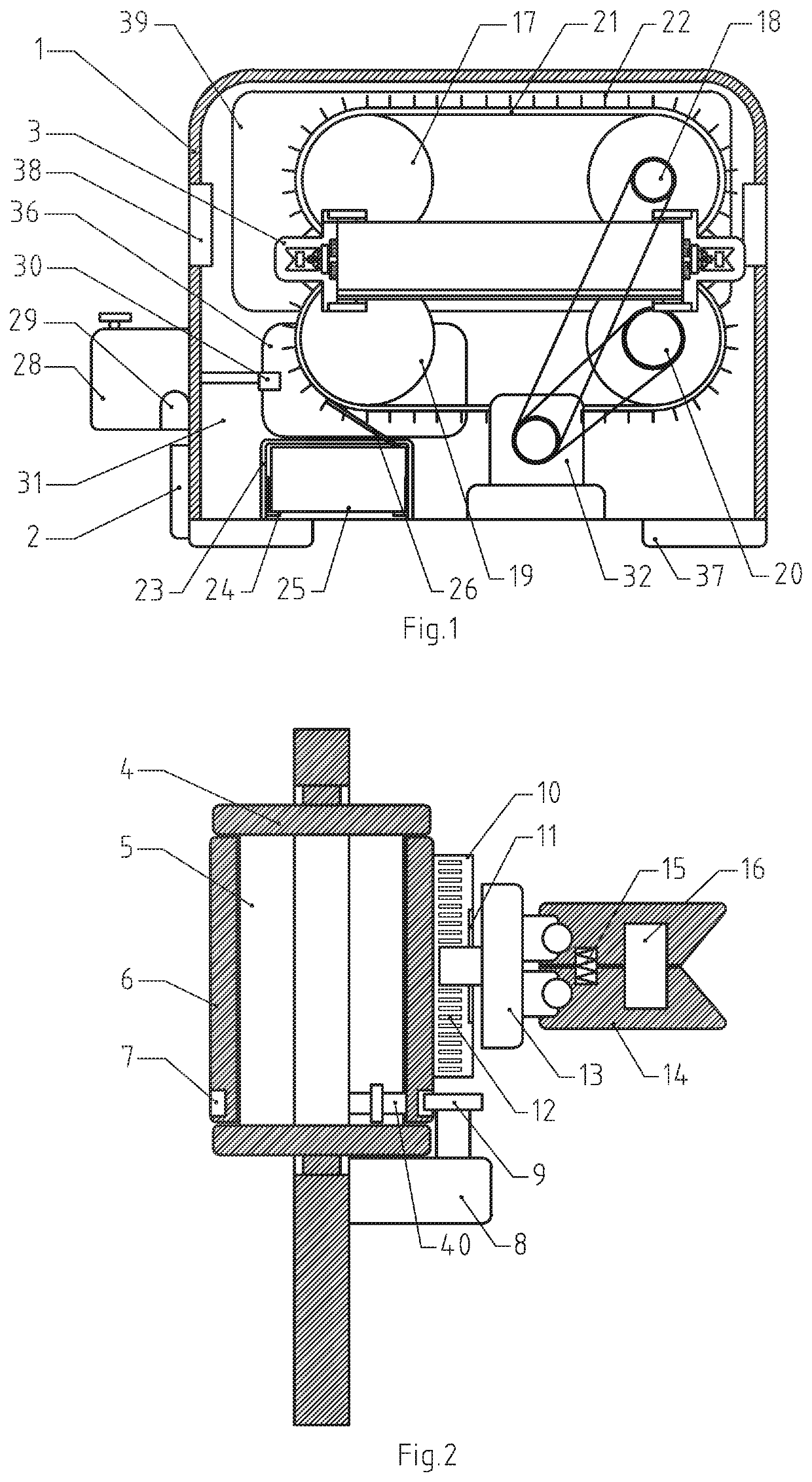
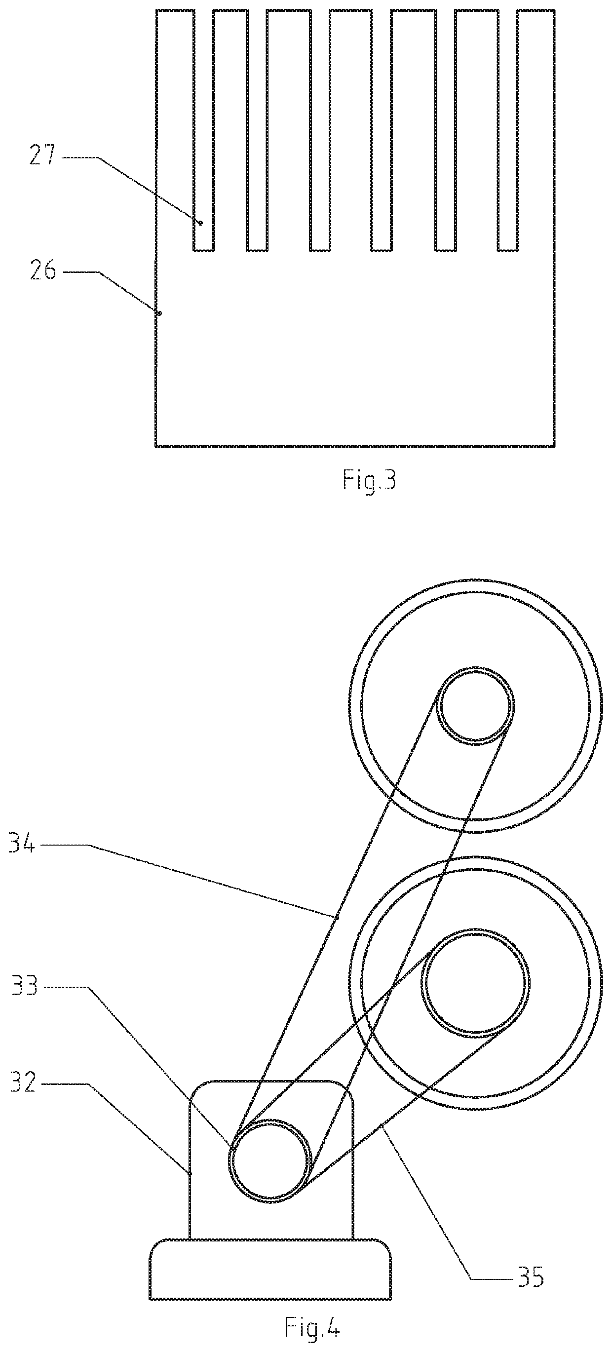
[0033]The present invention will be described in detail below with reference to drawings, as shown in FIGS. 1-4.

[0034]In this embodiment, model of a controller 2 is 80051, a signal output end of the controller 2 is electrically connected to signal input ends of a first electric motor 8, a second electric motor 32, and a suction pump 29, a power output terminal of the controller 2 is electrically connected to power input terminals of the first electric motor 8, the second electric motor 32 and the suction pump 29.

[0035]Creative point of the present invention includes structural design of bolt grease removal unit, referring to FIG. 1 and FIG. 2, the bolt grease removal unit drives a conveyor belt 6 to move by a first electric motor 8 so that bolts located outside a rectangular box 1 enter inside of the rectangular box 1, cleaning brushes 22 rotate while bolts move so as to achieve purpose of cleaning outer surface of the bolt. The bolt grease removal unit comprises a T-shaped opening ...

embodiment 2

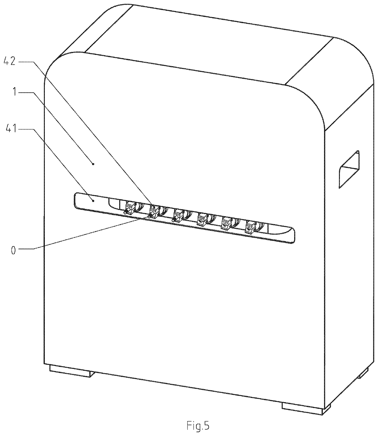
[0043]FIG. 5 shows a bolt grease removal device disclosed in this embodiment, a third opening 41 is provided on a front side of a rectangular box 1, and the third opening 41 exposes a clamping component 42 for clamping bolts. An operator places a bolt 0 to the clamping component 42 through the third opening 41, three clamping components 42 on left in FIG. 5 have clamped bolts 0, another three clamping components 42 on right in FIG. 5 have not clamped bolts 0 yet. The clamping component 42 uses movement of a conveyor belt 6 to bring bolts 0 into the rectangular box 1 for grease removal.

[0044]FIG. 6 and FIG. 16 show a main internal transmission structure of the bolt grease removal device disclosed in this embodiment. The main internal transmission structure comprises a first cleaning belt 211, a second cleaning belt 212, a conveyor belt 6, a second rack 43, and a third rack 44. Wherein the first cleaning belt 211 is driven by a first driven wheel 18, the second cleaning belt 212 is dr...


PUM

PropertyMeasurementUnit
magnetic forceaaaaaaaaaa
gravityaaaaaaaaaa
electromagnetic force adsorptionaaaaaaaaaa

Abstract

A device has a rectangular box, a roller driving unit and a controller are arranged to a side surface of the rectangular box, a grease removal unit is arranged to an inner surface of the rectangular box. The bolt grease removal device drives a conveyor belt to rotate through an electric motor, swing levers of clamping components play a role in fixing bolts, rotation of the conveyor belt drives bolts to make a circular motion to move bolts to a position of a cleaning brush to achieve an effect of removing grease on outer surface of bolt. Different rollers drive different cleaning brushes to rotate, use different sizes of driven wheels to make cleaning brushes have a certain relative speed to achieve an effect of rotating bolts and to increase the contact surface.

Description

CROSS-REFERENCE TO RELATED APPLICATIONS[0001]This application claims priority benefit of Chinese Patent Application No. 202010208666.1 filed on 23 Mar. 2020. The above-referenced application is hereby incorporated herein by reference.BACKGROUND OF THE INVENTION[0002]The invention relates to bolt cleaning devices, especially to bolt grease removal devices.[0003]There is a phenomenon of replacement of new and old metal products during use, a large amount of scrap metal may be produced every year due to corrosion, damage and natural elimination of metal products. Among them, there may be a large number of bolts scattered on the ground in production process of factory, these bolts can be reused after recycling. Patent application number 2018219075041 discloses a productive scrap metal recycling device, a second electromagnet and a third electromagnet are arranged on a top surface of a screening box in direction of a conveying mechanism, and a magnetic force generated by the second elect...

Claims


Application Information

Patent Timeline
Patent Type & Authority Patents(United States)
IPC IPC(8): A46B13/04B08B1/04A46B13/02B08B1/02B08B1/00B08B3/08A46B13/00B08B7/04
CPCA46B13/04A46B13/001A46B13/02B08B1/002B08B1/007B08B1/008B08B1/02B08B1/04B08B3/08B08B7/04A46B2200/3073B08B3/022B08B13/00B23G9/009
Inventor ZHU, GONG
Owner ZHU GONG
Why Eureka
Try Eureka