
Oven

a technology for ovens and ovens, applied in the field of ovens, can solve the problems of heat stroke, physical discomfort, and rise in the surrounding environment, and achieve the effects of avoiding the uncomfortably hot working environment of the oven, reducing the temperature of the hot air, and preventing the burning of the personnel around the oven

Active Publication Date: 2021-07-06
GRAND MATE
View PDF17 Cites 0 Cited by
  • Summary
  • Abstract
  • Description
  • Claims
  • Application Information

AI Technical Summary

Benefits of technology

Effectively utilizes heat energy to maintain food temperature, reduces energy consumption, and enhances safety by minimizing direct exposure to hot air, thereby improving working conditions and food preservation.

Problems solved by technology

It is well known that the heating device for cooking food, such as a stove, an oven, a roaster, or a griller, usually discharges the high temperature hot air generated during operation to the external of the heating device directly, which causes the temperature of the surrounding environment to rise.
For the personnel working in the high temperature environment, the hot atmosphere not only causes physical discomfort, but also leads to heat stroke if drinking water isn't replenished timely.
In severe cases, it may even cause heat exhaustion and shock.
In addition to the heath loss mentioned above, the personnel may suffer more direct injury, such as scald or burn, if they accidentally touch hot air.
In addition, the cooked food will cool easily after leaving the heating device and before being served on the table due to the lack of continuous heating.
Such repeated heating not only destroys the deliciousness of the food, but also wastes the energy for heating.
If the cooked food must be stored in the heat preservation device to avoid cooling, additional purchase of the heat preservation device is required, resulting in increase of the cost and energy consumption.
Generally, the thawing step either places the frozen food in the ambient environment or in the water, which takes time and affects the serving of subsequent meals.
Therefore, how to improve the above issues and lack, such as energy consumption, time consuming, and exposing the personnel to dangers, is the problem to be solved.

Method used


Image

  • Oven
  • Oven
  • Oven

Examples


Embodiment Construction

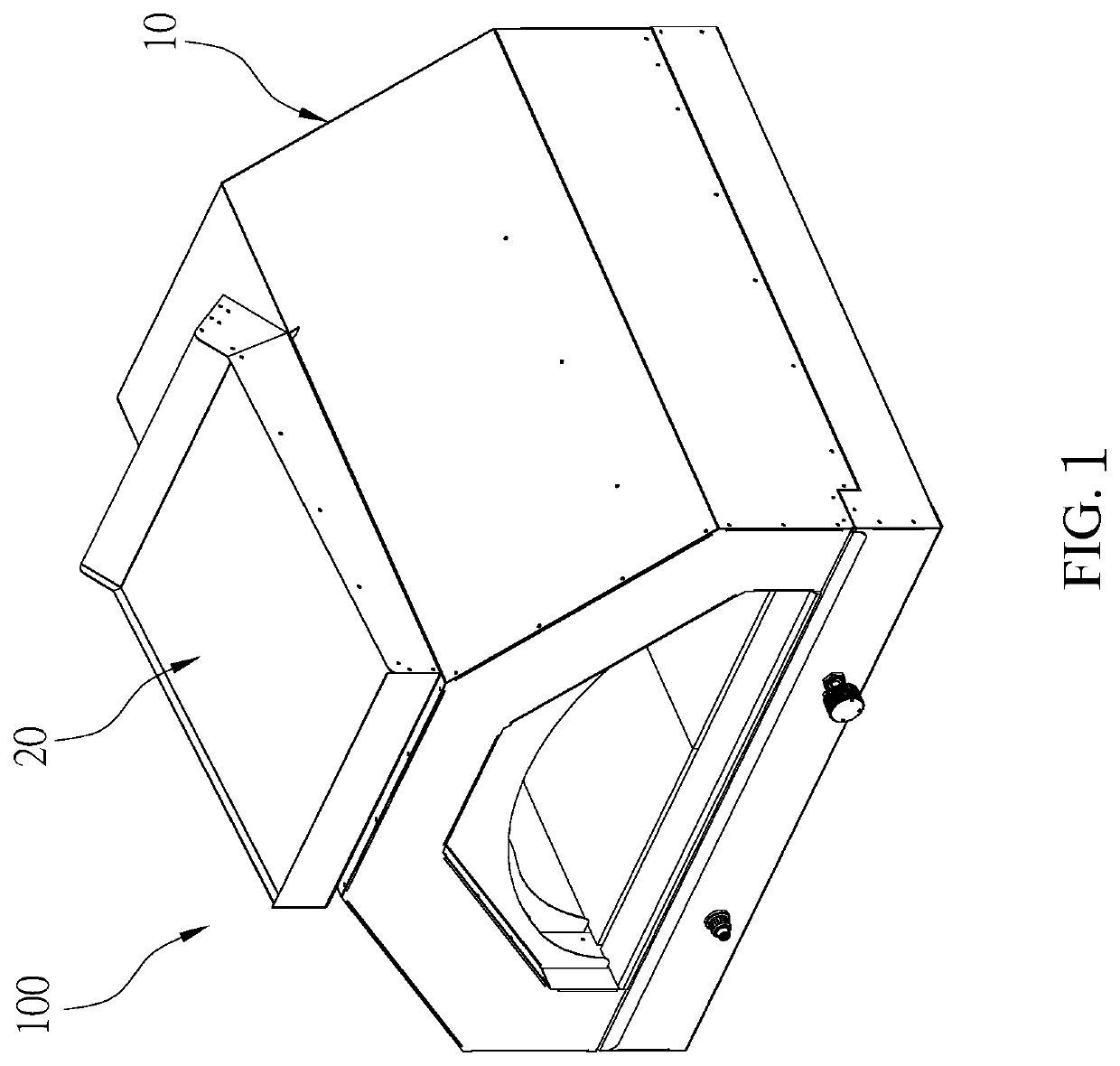
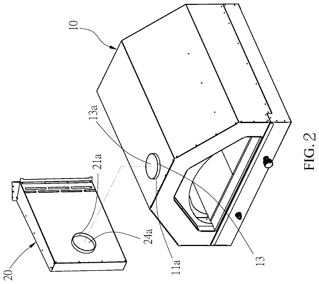
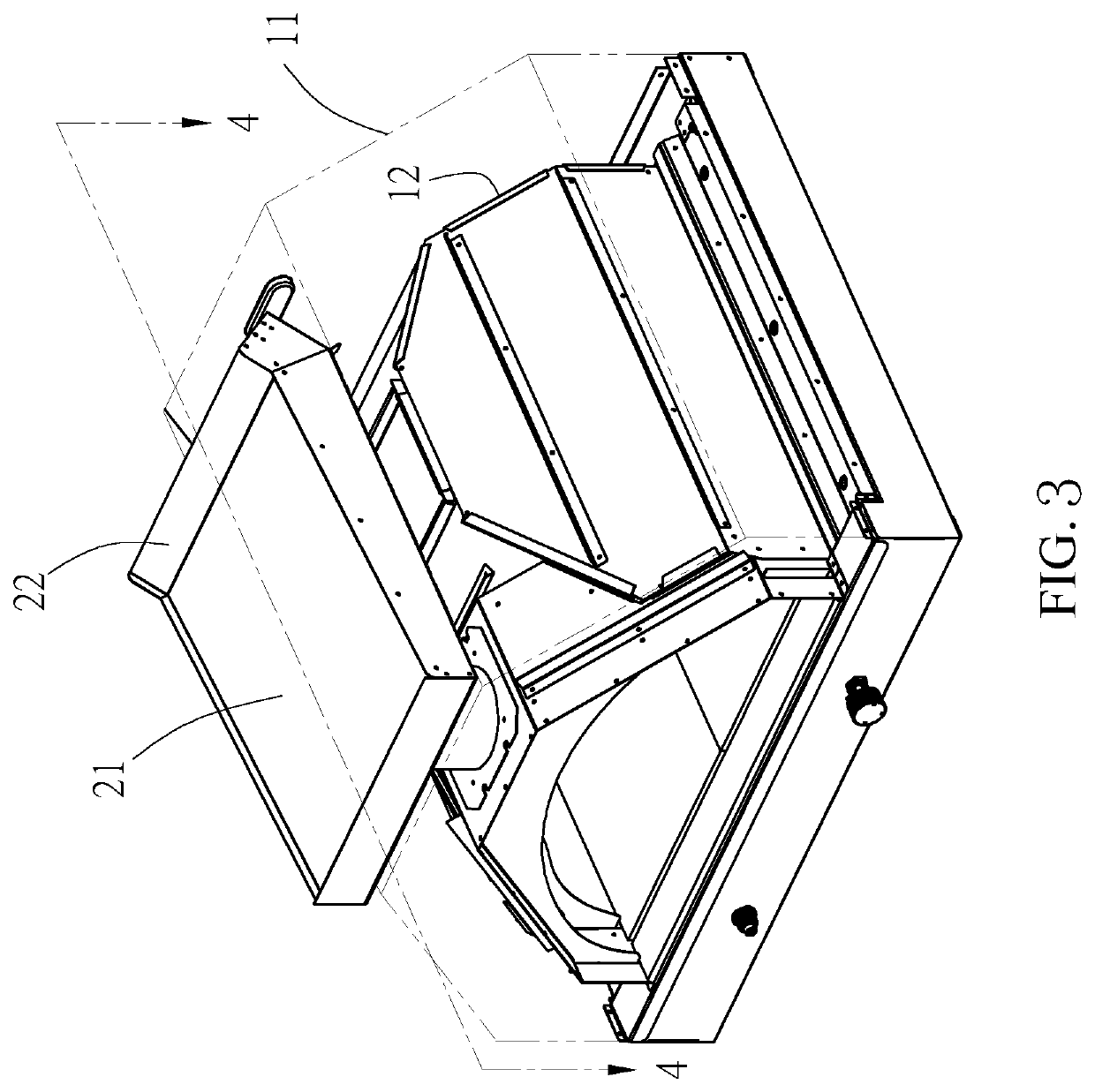
[0026]An oven 100 according to a first embodiment of the present invention is shown in FIG. 1 to FIG. 7 The oven 100 includes an oven body 10 and a heat transfer assembly 20. The oven body 10 has a casing 11, a main body 12 and an exhaust pipe 13. An opening 11a is formed on the top of the casing 11, and an opening 12a is formed on the top of the main body 12. A heat source (not shown) is provided in the main body 12 for heating. One end of the exhaust pipe 13 is connected to the opening 12a of the main body 12, and the other end of the exhaust pipe 13 is partially exposed to the external of the casing 11 through the opening 11a of the casing 11. Further, a heating device 12b is provided inside the main body 12, and the hot air generated by the heating device 12b turbulently flows upward along the exhaust pipe 13. In addition, an inlet is provided at the front side of the oven body 10 to communicate with the interior of the main body 12.

[0027]The heat transfer assembly 20 includes a...


PUM


Abstract

The present invention provides an oven including an oven body with an exhaust port and a heat transfer assembly, disposed at a side of the oven body, that includes a top plate and a bottom plate connected by two side plates, and a sealing plate to form an air passage therebetween. The air passage has a first opening near the sealing plate and a second opening away from the sealing plate. The first opening communicates with the exhaust port of the oven body, and the second opening opens to the external of the heat transfer assembly which is arranged so the hot air from the exhaust port may enter the interior of the heat transfer assembly so that the heat energy of the hot air can be absorbed by the top plate and then conducted to the food materials on the top plate to be reused.

Description

BACKGROUND OF THE INVENTIONTechnical Field[0001]The present invention is related to a baking equipment and, more particularly, to an oven that can fully utilize the heat of exhausted gas.Description of Related Art[0002]It is well known that the heating device for cooking food, such as a stove, an oven, a roaster, or a griller, usually discharges the high temperature hot air generated during operation to the external of the heating device directly, which causes the temperature of the surrounding environment to rise. For the personnel working in the high temperature environment, the hot atmosphere not only causes physical discomfort, but also leads to heat stroke if drinking water isn't replenished timely. In severe cases, it may even cause heat exhaustion and shock. In addition to the heath loss mentioned above, the personnel may suffer more direct injury, such as scald or burn, if they accidentally touch hot air.[0003]In addition, the cooked food will cool easily after leaving the h...

Claims


Application Information

Patent Timeline
Patent Type & Authority Patents(United States)
IPC IPC(8): F24C15/32F24C3/02
CPCF24C15/322F24C3/022F24C15/2007
Inventor HUANG, CHUNG-CHINHUANG, CHIN-YINGHUANG, HSIN-MINGHUANG, HSING-HSIUNGYEH, YEN-JENLIN, KUAN-CHOU
Owner GRAND MATE
Learn More