Time-resolved positron emission tomography encoder system for producing real-time, high resolution, three dimensional positron emission tomographic image without the necessity of performing image reconstruction

a tomographic encoder and encoder technology, applied in tomography, x/gamma/cosmic radiation measurement, instruments, etc., can solve the problems of inability to propose or develop, complicated process of finding the intersection of lors and identifying the exact location of positrons, and limited timing resolution of scintillator based optical detection systems. achieve the effect of more efficient and economical production

Active Publication Date: 2021-07-06
NUTT RONALD +1
View PDF371 Cites 3 Cited by
  • Summary
  • Abstract
  • Description
  • Claims
  • Application Information

AI Technical Summary

Benefits of technology

[0023]In an exemplary embodiment of the present general inventive concept, a new TPET imaging system capable of providing real-time, high resolution three-dimensional imagery is provided without the need for image reconstruction or CT correction of the attenuation of gamma rays. Whereas the radiation detectors provide X and Y coordinates, the third dimensional coordinate, i.e. the Z coordinate, is provided by measuring the time difference between two opposing detectors, (“ΔT”), between the gamma rays from a positron event being detected by two gamma ray detectors that are much faster than the scintillator detectors used in the conventional PET system. In order to provide this time measurement in real time, and in a manner that requires detection of significantly fewer events than traditional PET, rather than using a leading-edge timing discriminator and a traditional time encoder to determine a gamma event's location along the LOR, in an exemplary embodiment, TPET imaging system disclosed herein includes and utilizes a Constant Fraction Discriminator operating in conjunction with the Digital Intervalometer invented by the applicant herein. While the Constant Fraction Discriminator and the Digital Intervalometer could be utilized as discrete circuits, or separate chip sets, in an exemplary embodiment, the Constant Fraction Discriminator and the Digital Intervalometer are embedded on an Application Specific Integrated Circuit (“ASIC”). With this time measurement system, the arrival time of each photon in the annihilation process is recorded with respect to a clock frequency with picosecond resolution. In an exemplary embodiment, this TPET approach, requires significantly fewer gamma events, thus requiring fewer detectors, thereby resulting in a system that is more efficient and more economical to produce. By providing real-time, high resolution, artifact free images, the new TPET imaging system of the present general inventive concept allows real-time image comparisons of multiple organs thereby giving the clinician / diagnostician greater understanding of the relationships of multiple organ systems. Also, the new system allows the observation in real time of cancer lesions that are being treated by radiation or other means.

Problems solved by technology

It is known in the Positron Emission Tomography field that the state-of-the-art photomultiplier and relatively slow scintillators have limited the timing resolution of scintillator based optical detection systems for decades.
One can see from FIG. 1C that if the image has two locations of positrons the process of finding the intersection of LORs to identify the exact location of the positrons becomes more complicated.
This concept of TOF has been proposed in the literature and is available commercially, but designs that will produce acceptable high time resolution, a single view, and that use the time information to form the image directly have not been proposed or developed.
The problem with this technique is that many events are occurring in a short period of time; and, in order to provide real-time analysis, the system must be able to measure all of these events, and, in real-time, detect and isolate those events where the time difference falls within the desired field of view.
The statistical process requires a very large number of events, and thus, a large number of detectors, and, therefore, is very inefficient.
This process requires many more events than does the direct measurement of the TPET imaging system of the present general inventive concept and therefore is much more inefficient than the TPET imaging system disclosed herein.
It is known that this type of system is not capable of producing real-time, high resolution performance in the time domain or in the third dimension of the PET system for two additional reasons.
The first problem is the leading-edge timing used in the discriminators.
This is an unacceptably low resolution in the diagnostic imaging industry.
Further, it is known in the art that time walk associated with leading edge discriminators is undesirable; and that, even in cases in which the amplitude of the light signal does not vary appreciably, residual time walk can have a negative impact on time resolution.
A time-resolved PET imaging system offering real-time, high resolution imaging utilizing fewer detectors than traditional PET systems, and not requiring image reconstruction, is unavailable in the known art.
This produces a much more complicated PET system, and therefore a much more expensive system.

Method used


Image

  • Time-resolved positron emission tomography encoder system for producing real-time, high resolution, three dimensional positron emission tomographic image without the necessity of performing image reconstruction
  • Time-resolved positron emission tomography encoder system for producing real-time, high resolution, three dimensional positron emission tomographic image without the necessity of performing image reconstruction
  • Time-resolved positron emission tomography encoder system for producing real-time, high resolution, three dimensional positron emission tomographic image without the necessity of performing image reconstruction

Examples


Embodiment Construction

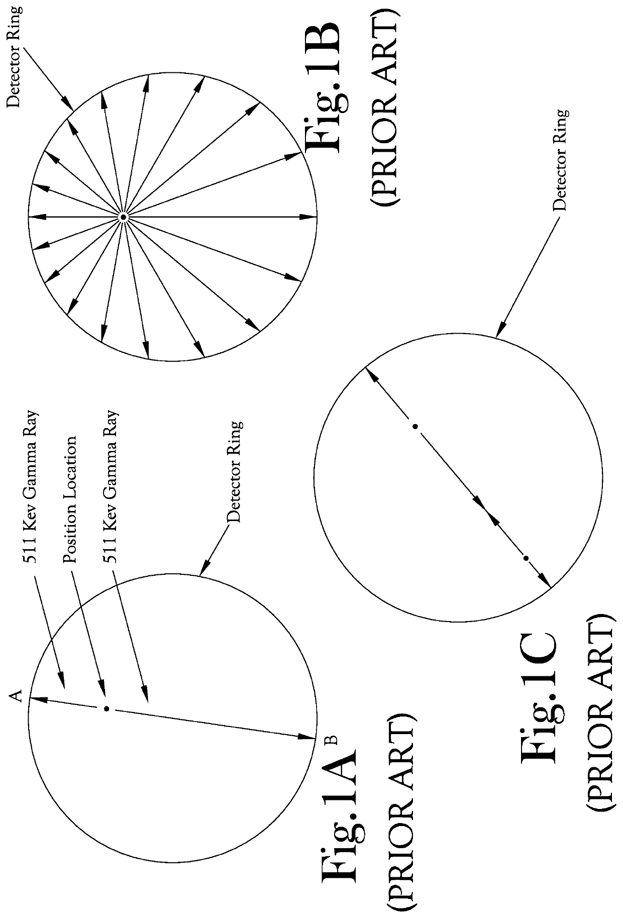
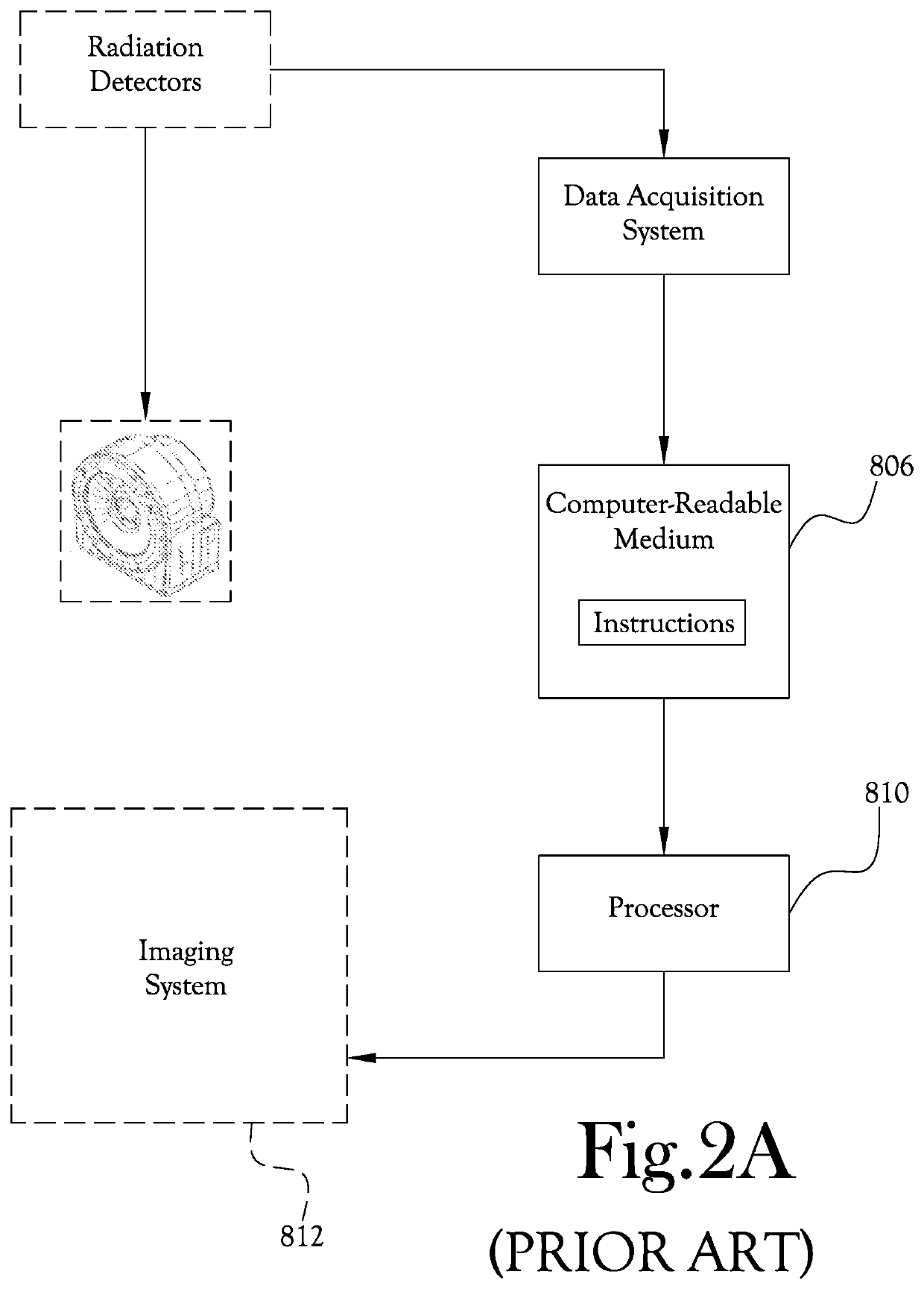
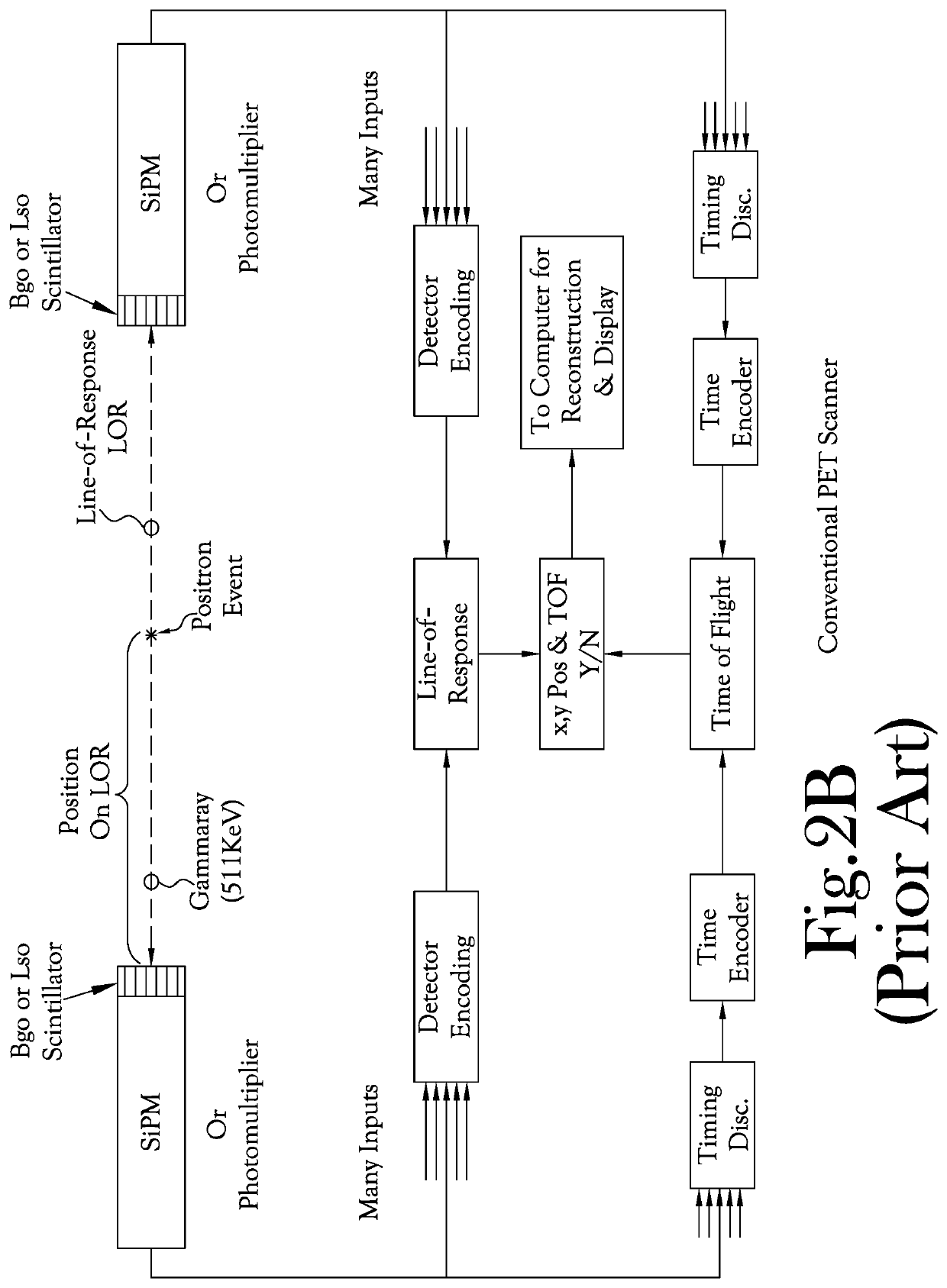
[0035]A new Time-Resolved Positron Emission Tomography, TPET, system 10 capable of providing real-time, high resolution, three-dimensional imagery is illustrated in FIGS. 5, 6A, 6B, 7A, and 7B. It will be understood that in state-of-the-art PET imagery, the normal LOR 20 is determined by standard block detectors 30A and 30B, which, as will be understood, are diametrically opposed to one another, and measure the gamma ray position, in both the X and Y coordinates, 40 and 50 respectively, in two dimensional space as schematically illustrated in FIG. 7A. FIG. 5 depicts a TPET imaging system of the present general inventive concept. FIG. 5 represents the TPET imaging system showing the required two parallel plates of detectors, 30A and 30B, having typically a factor of ten fewer detectors than the prior art.

[0036]In FIGS. 7A and 7B, the positron events, such as positron event 75 in FIG. 7A, that is occurring in the organ 70, is illustrated schematically. Referring to FIGS. 7A and 7B, th...


PUM


Abstract

A Time-Resolved PET imaging system for producing real-time, high resolution, three-dimensional positron emission tomographic images without performing sinogram formation or image reconstruction. The third dimension is provided by measuring the ΔT between the arrival times of gamma rays from a positron event being detected by two cooperating detectors. In order to determine the location of a positron event along the lines of response, the measurement includes a fast scintillator, constant fraction discriminator and the digital intervalometer. The arrival time of each photon in the annihilation process is recorded with respect to a clock frequency with picosecond resolution. This approach requires significantly fewer positron events, thus requiring fewer detectors, thereby resulting in a new, real-time TPET imaging system that is more efficient and more economical to produce than conventional PET systems.

Description

CROSS-REFERENCE TO RELATED APPLICATIONS[0001]This application claims the benefit of U.S. Non-Provisional patent application Ser. No. 16 / 857,499, filed on Apr. 24, 2020, which is incorporated herein in its entirety by reference.STATEMENT REGARDING FEDERALLY SPONSORED RESEARCH OR DEVELOPMENT[0002]Not ApplicableBACKGROUND OF THE INVENTION1. Field of Invention[0003]The present general inventive concept relates to a new Time-Resolved Positron Emission Tomography system, (“TPET”). More particularly, it relates to a much simpler Time-Resolved PET Imaging System offering real-time imaging, requiring only a single view, fewer detectors, and producing high resolution PET imagery without the necessity of performing image reconstruction.2. Description of the Related Art[0004]When a positron decays it produces two gamma rays that have directions 180 degrees opposed to one another, (see FIG. 1A). While there is a small error in the angle due to the momentum of the positron, for Positron Emission ...

Claims


Application Information

Patent Timeline
Patent Type & Authority Patents(United States)
IPC IPC(8): G01T1/29A61B6/03A61B6/00
CPCG01T1/2985A61B6/037A61B6/4216A61B6/4266A61B6/5205
Inventor NUTT, RONALDNUTT, LYNDA J.
Owner NUTT RONALD
Why Eureka
Try Eureka