
Display panel applicable to reducing noise coupling and enhancing sensing signal in optical fingerprint sensor thereof with aid of switch arrangement, and associated electronic device

a technology of optical fingerprint sensor and switch arrangement, applied in the field of display panel, can solve the problems of reducing affecting the overall performance of the device, so as to enhance the sensing signal, and reduce the noise coupling

Active Publication Date: 2021-07-06
HIMAX TECH LTD
View PDF6 Cites 0 Cited by
  • Summary
  • Abstract
  • Description
  • Claims
  • Application Information

AI Technical Summary

Benefits of technology

[0006]It is another objective of the present invention to provide a display panel and an associated electronic device, in order to enhance overall performance of the display panel.
[0009]The present invention display panel and associated electronic device can guarantee that the whole system (e.g. the electronic device) can operate properly, to prevent the related art problems. In addition, the present invention display panel is applicable to reducing noise coupling and enhancing sensing signals in an optical fingerprint sensor thereof (which may comprise the plurality of light sensors) with aid of switch arrangement, to enhance the overall performance.

Problems solved by technology

The traces between the optical fingerprint sensor and the detection circuit are quite long, and parasitic capacitance is typically unavoidable.
More particularly, the current generated by a PD is typically very weak (e.g. 1 pico-ampere (pA)), and there may be various sources of noise, causing difficulty of signal detection.
As a result, the output signal OUT_SE of the detection circuit cannot accurately indicate a corresponding portion of a fingerprint.
In addition, for normal operations of the PDs, a bias voltage VCM is typically required, and any jitter of this voltage may also affect the signal received by the detection circuit.
Additionally, the parasitic capacitance such as Cload may exist on the traces, and noise may be coupled through it if there is noise at the other side thereof.

Method used


Image

  • Display panel applicable to reducing noise coupling and enhancing sensing signal in optical fingerprint sensor thereof with aid of switch arrangement, and associated electronic device
  • Display panel applicable to reducing noise coupling and enhancing sensing signal in optical fingerprint sensor thereof with aid of switch arrangement, and associated electronic device
  • Display panel applicable to reducing noise coupling and enhancing sensing signal in optical fingerprint sensor thereof with aid of switch arrangement, and associated electronic device

Examples


Embodiment Construction

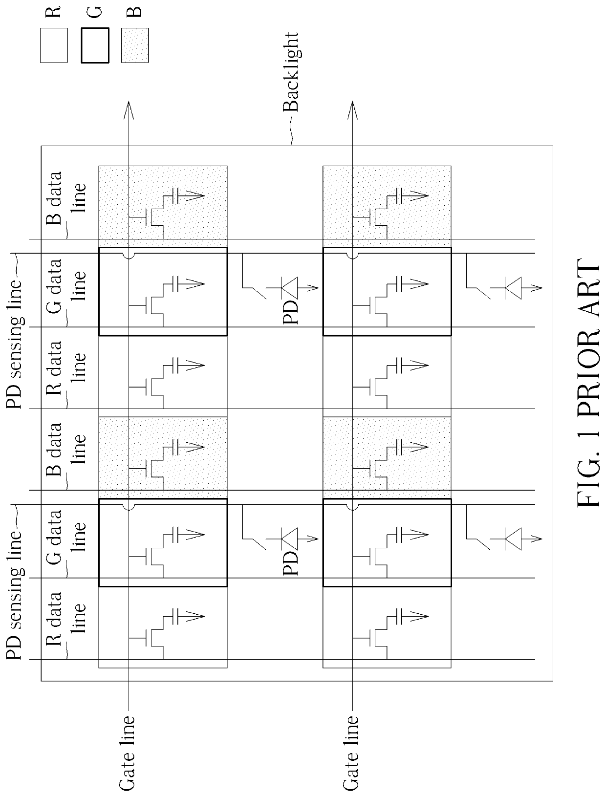
[0023]FIG. 5 is a circuit diagram of a display panel 100 comprising an enhancement type optical fingerprint sensor according to an embodiment of the present invention. The display panel 100 may comprise a plurality of display blocks arranged to display images, and each of the plurality of display blocks may comprise one or more display units. For better comprehension, the plurality of display blocks of the display panel 100 may be implemented according to the example shown in FIG. 1, and therefore, the one or more display units may comprise R, G, and B display units, and the display panel 100 may further comprise gate lines, data lines (e.g. R, G, and B data lines), and a backlight such as that shown in FIG. 1, but the present invention is not limited thereto. More particularly, the display panel 100 (e.g. the enhancement type optical fingerprint sensor) may comprise a plurality of light sensors (e.g. a plurality of PDs) that may be arranged in a plurality of dual-set modules {110} ...


PUM


Abstract

A display panel and an associated electronic device are provided. The display panel may include: a plurality of display blocks arranged to display images, a plurality of light sensors arranged to perform light sensing, a plurality of sets of switches, and a detection circuit. The plurality of sets of switches may combine the plurality of light sensors into a plurality of combined sensors, respectively, wherein the plurality of sets of switches operate according to a plurality of switching signals, respectively. The detection circuit may be coupled to two sets of combined sensors within the plurality of combined sensors, and arranged to detect a voltage level of a combined sensor of one set of the two sets of combined sensors according to a reference voltage level, for performing fingerprint detection through the display panel, wherein the reference voltage level is obtained from another set of the two sets of combined sensors.

Description

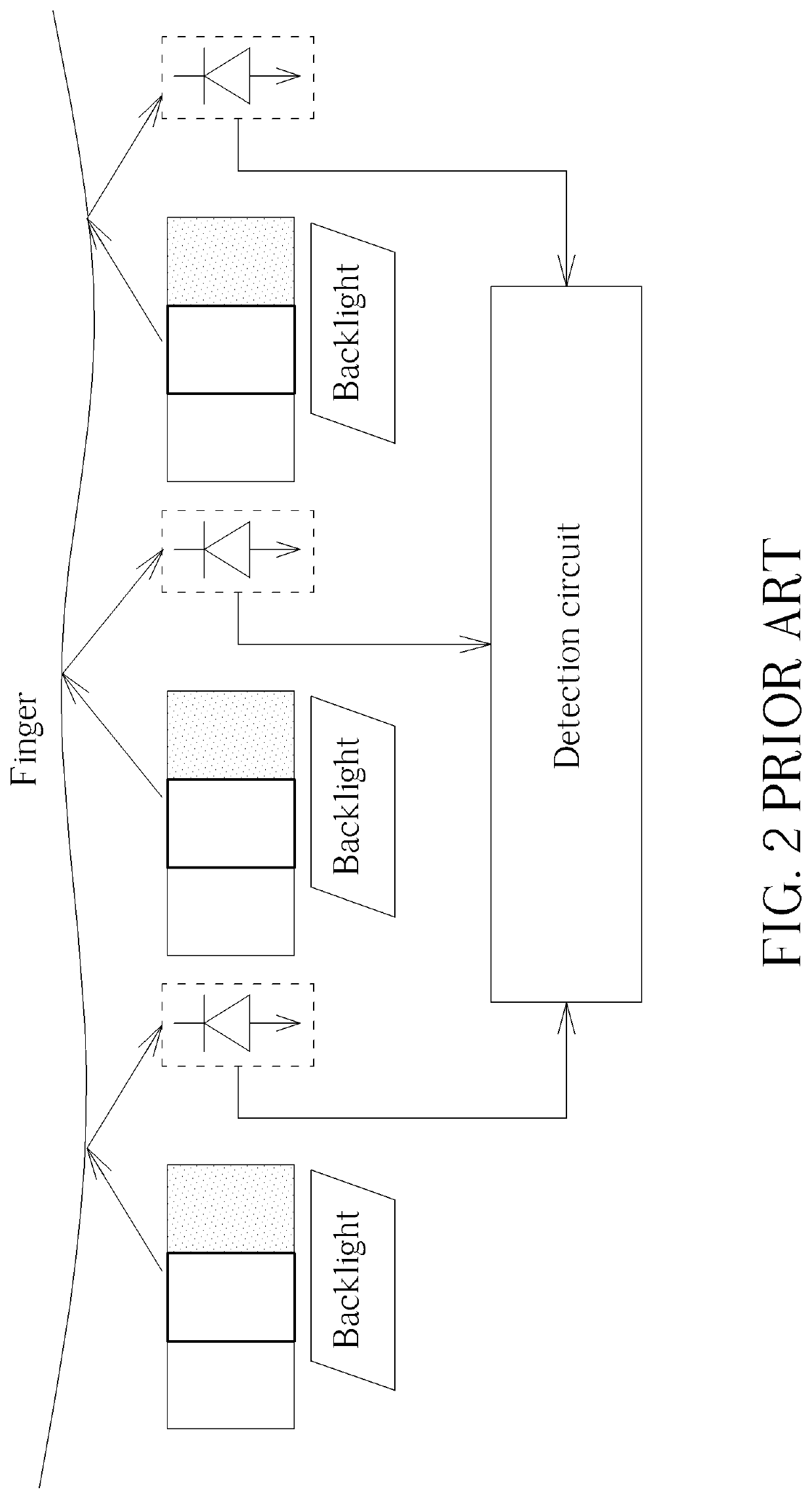
BACKGROUND OF THE INVENTION1. Field of the Invention[0001]The present invention is related to display devices, and more particularly, to a display panel applicable to reducing noise coupling and enhancing sensing signals in an optical fingerprint sensor thereof with aid of switch arrangement, and an associated electronic device.2. Description of the Prior Art[0002]FIG. 1 illustrates an example of a display panel. The display panel may comprise a backlight, display units such as red (R), green (G), and blue (B) display units, gate lines, data lines such as R, G, and B data lines, photo detectors (PDs), and PD sensing lines, where the legend such as R, G, and B may indicate the respective colors of the display units. An example of fingerprint detection may be illustrated as shown in FIG. 2. Respective portions of the backlight may provide light through the R, G, and B display units. The surface of a finger (e.g. fingertip thereof) may reflect a portion of the light, and the PDs may re...

Claims


Application Information

Patent Timeline
Patent Type & Authority Patents(United States)
IPC IPC(8): G09G3/3233G06K9/00G09G3/20G09G3/3241
CPCG06K9/0004G09G3/20G09G3/3241G09G2300/0426G06V40/1318
Inventor HE, JIA-MINGCHANG, YAW-GUANGWU, I-LIN
Owner HIMAX TECH LTD
Learn More