Slip ring transmitter for rotary-table machines

a technology transmitters, which is applied in the direction of current collectors, dynamo-electric machines, current collector maintenance, etc., can solve the problems of graphite brushes, signal units, high maintenance, etc., and achieves high data rate, convenient maintenance of rotary table machines, and flexible slip tracks.

a technology transmitters, which is applied in the direction of current collectors, dynamo-electric machines, current collector maintenance, etc., can solve the problems of graphite brushes, signal units, high maintenance, etc., and achieves high data rate, convenient maintenance of rotary table machines, and flexible slip tracks.

US11056849B2Active Publication Date: 2021-07-06KRONES AG

Image

  • Slip ring transmitter for rotary-table machines
  • Slip ring transmitter for rotary-table machines
  • Slip ring transmitter for rotary-table machines

Examples


Embodiment Construction

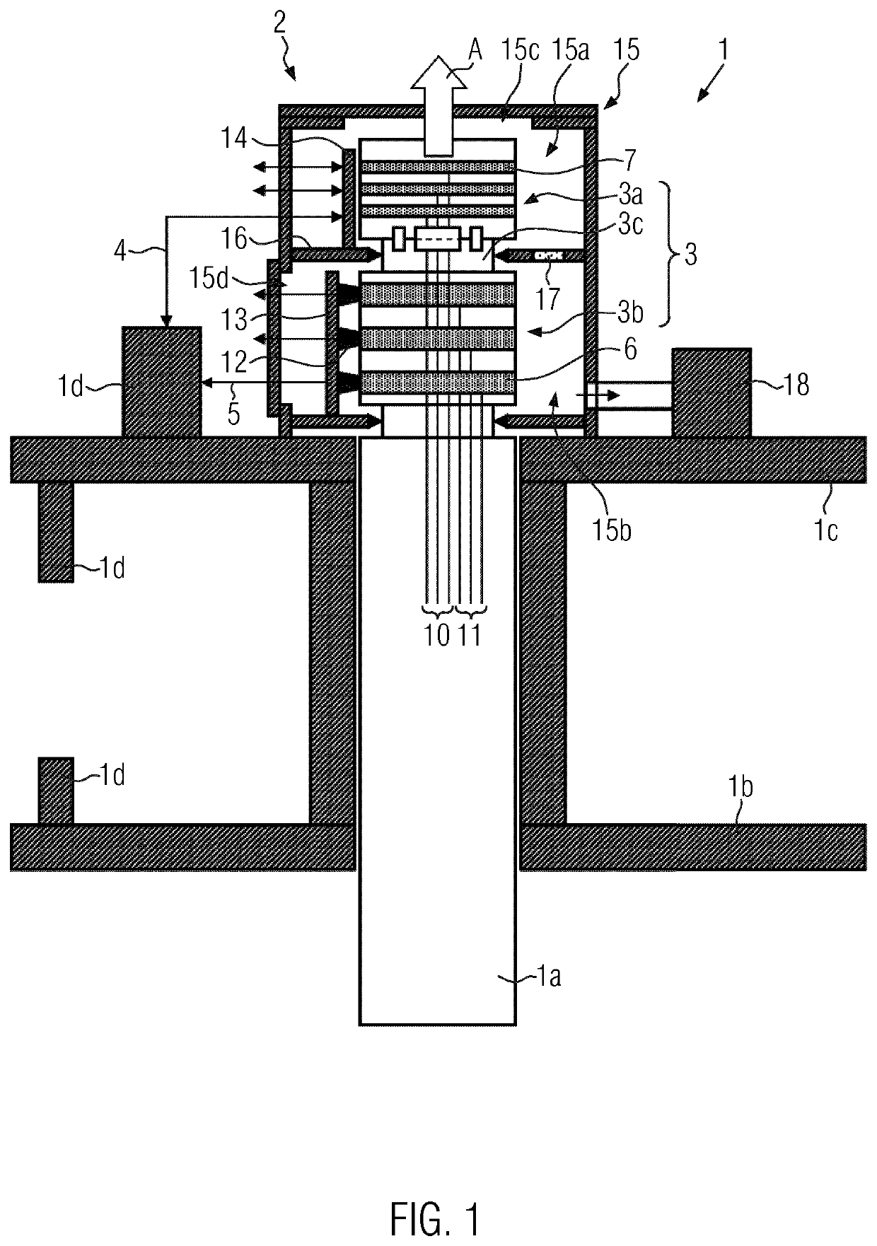
[0036]As is evident from FIG. 1 in a schematic partial view of a rotary-table machine 1, slip ring transmitter 2 according to the invention comprises a slip ring 3 with a signal unit 3a for transmitting signals and / or data 4 and with a power unit 3b for transmitting electrical power 5.

[0037]Signal unit 3a and power unit 3b are formed as modules that are detachable from each other. In particular, signal unit 3a can be detached from power unit 3b installed in slip ring transmitter 2, for example, for maintenance measures. For this purpose, signal unit 3a can preferably be drawn off in the axial direction A from power unit 3b.

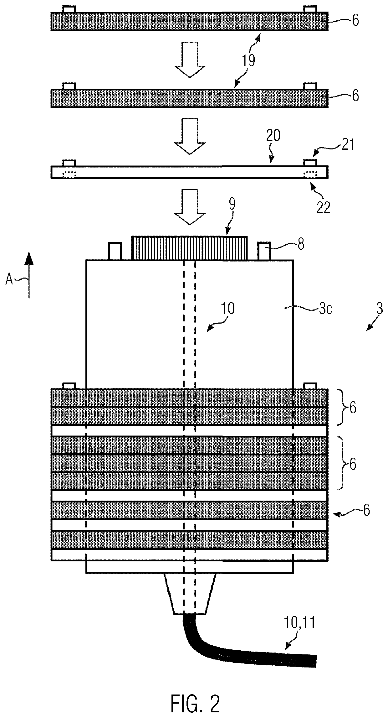
[0038]Power unit 3b comprises slip tracks 6 which have, for example, contact surfaces made of brass, gold alloy or silver alloy. Signal unit 3a comprises ring tracks 7 which are preferably designed for non-contact transmission of signals and / or data 4 by way of a capacitive, optical or inductive coupling. For the sake of simplicity, three slip tracks 6 and three ...


PUM


Abstract

A slip ring transmitter for electrically connecting assemblies of rotary-table machines is described and comprises a slip ring with a signal unit for transmitting signals and / or data and with a power unit for transmitting electrical power. As the signal unit is formed such that it is modularly detachable can in particular be axially drawn off from the power unit, the signal unit can be inspected and / or replaced separately from the power unit. This improves the reliability of the transmission of signals and / or data and enables individual optimization of the power unit.

Description

CROSS-REFERENCE TO RELATED APPLICATIONS[0001]The present application is a U.S. National Phase of International Patent Application Serial No. PCT / EP2016 / 081261 entitled “SLIP-RING TRANSMITTER FOR ROTARY-TABLE MACHINES,” filed on Dec. 15, 2016. International Patent Application Serial No. PCT / EP2016 / 081261 claims priority to German Patent Application No. 10 2016 203 762.5, filed on Mar. 8, 2016. The entire contents of each of the abovementioned applications are hereby incorporated by reference in their entirety for all purposes.TECHNICAL FIELD[0002]Rotary-table machines with at least one stationary assembly and at least one rotating assembly are known to be used for the production of plastic bottles and for processing plastic bottles and glass bottles, for example, by inspection, labeling and / or filling, in bottling systems. Slip ring transmitters are used for transmitting electrical signals, such as control signals and data, and for transmitting electrical power to supply consumers in...

Claims


Application Information

Patent Timeline
06 Jul 2021
Publication
US11056849B2
IPC
H01R39/14; H01R39/08; H02K11/33; H02K11/35; H01R39/58; H01R43/14; H02K13/00
CPC
H01R39/08; H01R39/58; H01R43/14; H02K11/33; H02K11/35; H02K13/003
Inventors
SIXT, ROBERT; KUMAR, ROHIT