Semiconductor structure and method of forming a semiconductor structure

a technology of semiconductor structure and semiconductor structure, which is applied in the direction of semiconductor devices, semiconductor/solid-state device details, electrical apparatus, etc., can solve the problems of worse control capability of gate for corresponding channels, and achieve the effect of enhancing heat dissipation effect, widening width, and increasing the volume of the bottom fin

Active Publication Date: 2021-07-27
SEMICONDUCTOR MANUFACTURING INTERNATIONAL (BEIJING) CORP +1
View PDF1 Cites 0 Cited by
  • Summary
  • Abstract
  • Description
  • Claims
  • Application Information

AI Technical Summary

Benefits of technology

[0004]To better adapt to the reduction of the CD, a semiconductor process gradually begins a transition from a planar MOSFET to a three-dimensional transistor having higher efficacy, such as a fin field effect transistor (FinFET). In the FinFET, a gate structure may control an ultra thin body (fin) from at least two sides. Compared with the planar MOSFET, the gate structure has a stronger control capability for the channel, and can well suppress the short-channel effect; and compared with other devices, the FinFET can be better compatible with the existing integrated circuit manufacturing.
[0008]When compared with the prior art, technical solutions of embodiments and implementations of the present disclosure have one or more of the following advantages:
[0009]In some implementations, after a base is patterned, a formed fin includes a bottom fin and a top fin located on the bottom fin, and in a direction perpendicular to an extension direction of the fin, a width of the top fin is less than a width of the bottom fin; a bottom fin with a larger width is formed, to increase the volume of the bottom fin, and the area of a contact surface of the fin and a substrate, and to correspondingly enhance an effect of dissipating heat generated during working of a device to the substrate, thereby improving the heat dissipation performance of the device, and to correspondingly improve a self-heating effect of the device, so that the device performance is further improved.
[0010]In some implementations, after the top fin is formed, a sidewall layer is formed on a sidewall of the top fin, and second patterning processing is performed on the residual base exposed by the top fin by using the sidewall layer as a mask, to form the bottom fin. The sidewall layer is formed on the sidewall of the top fin, so that the width of the bottom fin can be easily controlled by controlling the thickness of the sidewall layer, to help reduce the process difficulty in forming the bottom fin, and improve the width accuracy of the bottom fin.
[0011]In some implementations, the base includes a device unit region, and the device unit region includes a central region and an edge region located on two sides of the central region. After the second patterning processing, a bottom fin of the central region is an integral structure, to further increase the volume of the bottom fin of the central region, and the area of a contact surface of a fin and a substrate of the central region, thereby further improving the self-heating effect of the device.

Problems solved by technology

Therefore, a control capability of a gate for a corresponding channel becomes worse, and it is increasingly difficult for a gate voltage to pinch off the channel, so that a subthreshold leakage phenomenon, that is, a so-called short-channel effect (SCE) occurs more easily.

Method used


Image

  • Semiconductor structure and method of forming a semiconductor structure
  • Semiconductor structure and method of forming a semiconductor structure
  • Semiconductor structure and method of forming a semiconductor structure

Examples


Embodiment Construction

[0014]At present, after a fin structure is introduced to a semiconductor structure, the device performance is easily degraded. The cause of the performance degradation is as follows:

[0015]Compared with a planar transistor, a space occupied by an isolation structure in a FinFET is enlarged, and the area of a contact surface of a fin and a substrate is relatively small, thereby worsening a heat dissipation effect of a device. Further, the material of the isolation structure is generally silicon oxide, which has a smaller heat conductivity coefficient compared with the material of the substrate, thereby further worsening the heat dissipation effect of the device, and causing a more severe self-heating effect of the device, and correspondingly more severe performance degradation of the device.

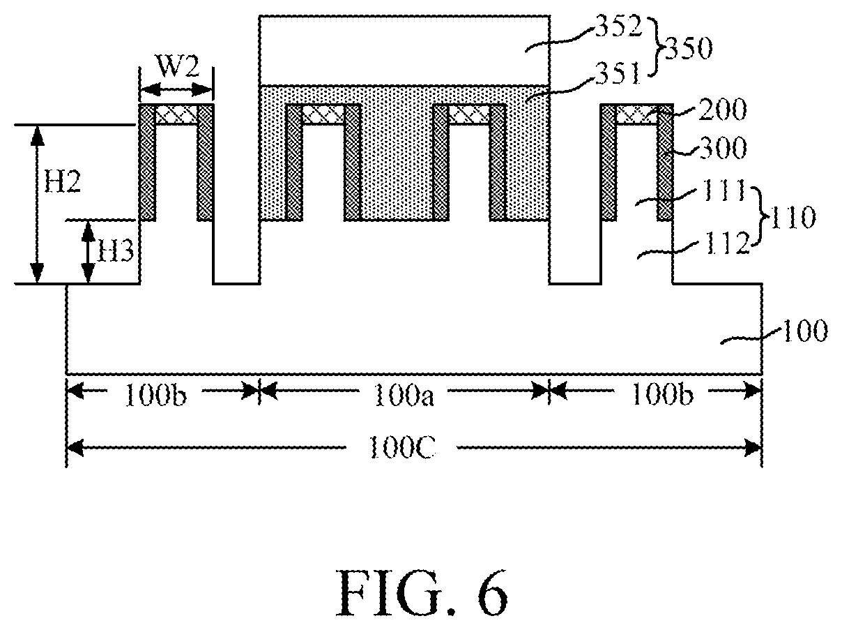
[0016]To address the technical problem, in some implementations of the present disclosure, a formed fin includes a bottom fin and a top fin located on the bottom fin, where a width of the bottom fi...


PUM

PropertyMeasurementUnit
pressureaaaaaaaaaa
semiconductor structureaaaaaaaaaa
widthaaaaaaaaaa

Abstract

A semiconductor structure and a method for forming a semiconductor structure are disclosed. A form of a method for forming a semiconductor structure includes: providing a base; patterning the base, to form a substrate and fins protruding out of the substrate, where each fin includes a bottom fin and a top fin located on the bottom fin, and in a direction perpendicular to an extension direction of each fin, a width of the top fin is less than a width of the bottom fin; and forming an isolation structure on the substrate exposed by a fin, where the isolation structure covers at least a sidewall of the bottom fin, and a top of the isolation structure is lower than a top of the fin. In the present disclosure, a bottom fin with a larger width is formed, to increase the volume of the bottom fin, and the area of a contact surface of the fin and the substrate, and to correspondingly enhance an effect of dissipating heat generated during working of a device to the substrate, thereby improving the heat dissipation performance of the device, and to correspondingly improving a self-heating effect of the device, so that the device performance is further improved.

Description

RELATED APPLICATIONS[0001]The present application claims priority to Chinese Patent Appln. No. 201811368089.1, filed Nov. 16, 2018, the entire disclosure of which is hereby incorporated by reference.BACKGROUNDTechnical Field[0002]Embodiments and implementations of the present disclosure relate to the field of semiconductor manufacturing, and in particular, to a semiconductor structure and a forming method thereof.Related Art[0003]In semiconductor manufacturing, with a development tendency of ultra-large-scale integrated circuits, a critical dimension (CD) of an integrated circuit is regularly being reduced. To adapt to the reduction of the CD, a corresponding channel length of a MOSFET is also regularly reduced. However, with the shortening of the channel length of a device, a corresponding distance between a source and a drain of the device is also shortened. Therefore, a control capability of a gate for a corresponding channel becomes worse, and it is increasingly difficult for a ...

Claims


Application Information

Patent Timeline
Patent Type & Authority Patents(United States)
IPC IPC(8): H01L29/66H01L29/78H01L21/8234H01L27/088H01L23/367H01L23/34
CPCH01L23/367H01L21/823431H01L21/823481H01L23/345H01L27/0886H01L29/66795H01L29/785H01L29/0684
Inventor ZHOU, FEI
Owner SEMICONDUCTOR MANUFACTURING INTERNATIONAL (BEIJING) CORP
Why Eureka
Try Eureka