Control systems and prediction methods for it cooling performance in containment

a control system and containment technology, applied in adaptive control, cooling/ventilation/heating modification, instruments, etc., can solve problems such as airflow mismatch between cooling units and information technology (it) equipment, and not representative of it equipment reliability, so as to reduce the amount of available cold air, reduce the capacity, and improve the effect of cooling efficiency

Active Publication Date: 2021-07-27
THE RES FOUND OF STATE UNIV OF NEW YORK
View PDF1049 Cites 26 Cited by
  • Summary
  • Abstract
  • Description
  • Claims
  • Application Information

AI Technical Summary

Benefits of technology

[0051]All this data feeds into a central controller that can specify the cooling region per IT equipment item, and give early indications of internal heating. This assists in avoiding CPU thermal throttling, which degrades application delivery and increases latency. That is, the central controller seeks to predict internal thermal (and secondary) feedback mechanisms within the IT equipment, and to maintain environmental conditions such that these internal feedback mechanisms do not unnecessarily degrade performance. In some cases, these mechanisms may be exploited, but since they are difficult to explicitly control, and reduce performance, generally they are relied upon as a backup safety measure and not a primary control mechanism, according to the present invention.
[0074]The method may further comprise detecting an airflow reduction in the cold air cooling system, and imposing a power cap on certain information technology equipment with relatively higher capacity cooling fans to mitigate a reduction in available cold air to other information technology equipment with relatively lower capacity cooling fans.

Problems solved by technology

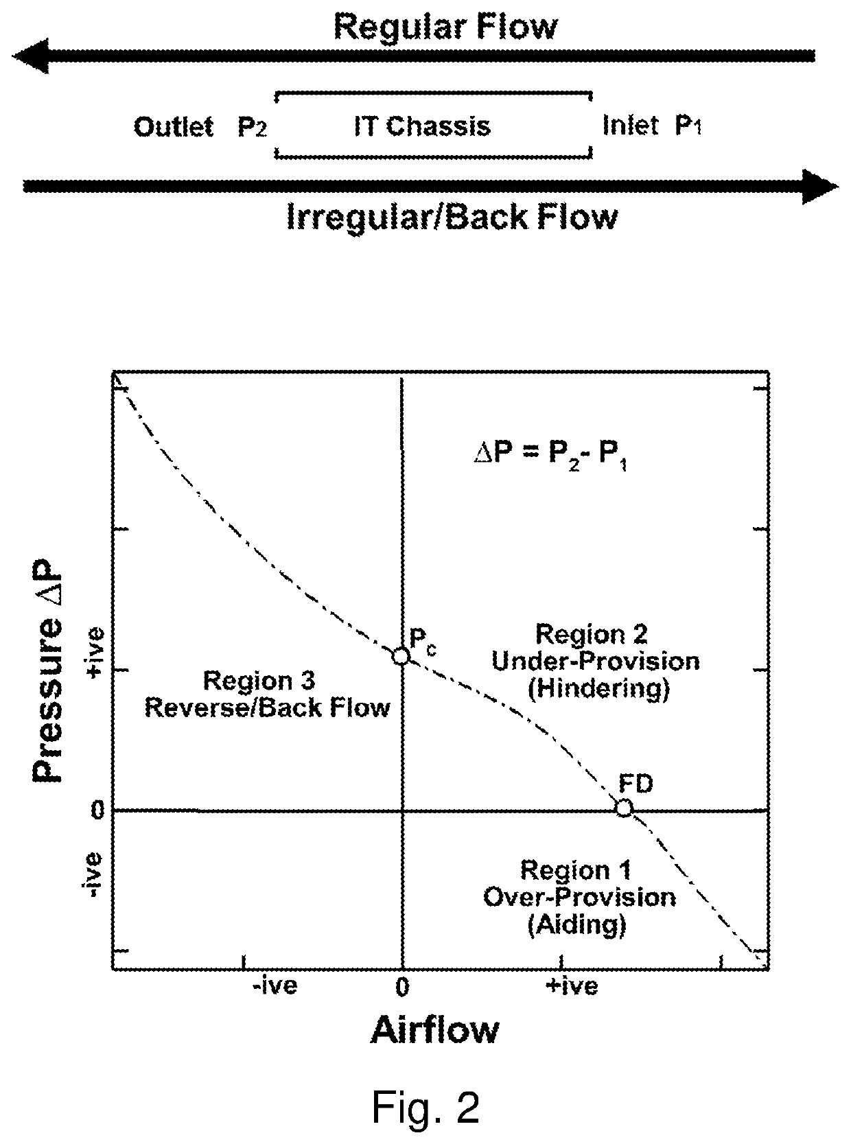
The challenge for such systems is that an airflow mismatch between cooling units and information technology (IT) equipment is possible.
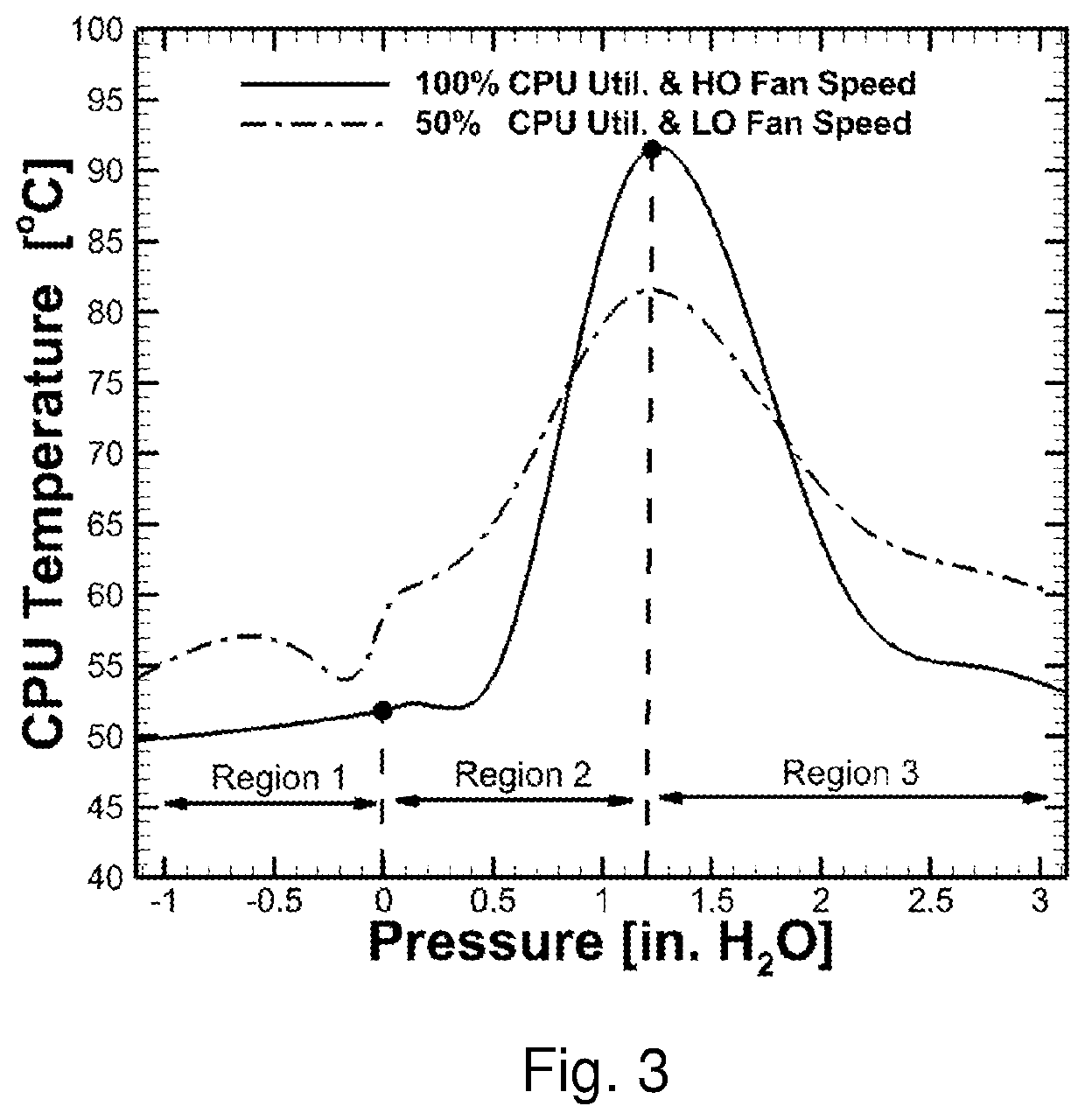
During any case of airflow mismatch, the classical Data Center Infrastructure Management (DCIM) monitoring inlet sensors become discontinuous from Intelligent Platform Management Interface (IPMI) analytics, but also not representative of the IT equipment reliability.
This happens because the external temperature sensors are agnostic to the heating rates of internal components that accelerate inside the server due to the airflow reduction.

Method used


Image

  • Control systems and prediction methods for it cooling performance in containment
  • Control systems and prediction methods for it cooling performance in containment
  • Control systems and prediction methods for it cooling performance in containment

Examples


Embodiment Construction

[0078]Generally, a legacy data center consists of an array of hot and cold aisles where the air intake to the IT equipment resides in the cold aisle and the air exhaust of the equipment rejects hot air into the hot aisle. In a raised floor environment, chilled air is supplied through the plenum to the cold aisle. The heated air in the hot aisle flow backs to the cooling unit return.

[0079]However, the recirculation of air from hot to cold aisles or vice versa is a common occurrence. This air recirculation endangers the well-being of servers and reduces data center cooling efficiency, resulting in an increased total cost of operation. To resolve these issues cold or hot aisle containment (CAC or HAC) solutions were introduced to segregate the incoming cold air stream from the heated exhaust stream. CAC or HAC cooling solutions allow higher chilled set point temperature and can enhance the performance of an air side economizer, which admits outside air to the cool air stream (when outs...


PUM


Abstract

A method of controlling a data center having a cold air cooling system, and at least one containment structure, comprising: determining a minimum performance constraint; determining optimum states of the cold air cooling system, a controlled leakage of air across the containment structure between a hot region and a cold air region, and information technology equipment for performing tasks to meet the minimum performance constraint, to minimize operating cost; and generating control signals to the cold air cooling system, a controlled leakage device, and the information technology equipment in accordance with the determined optimum states.

Description

CROSS REFERENCE TO RELATED APPLICATION[0001]The present application is a non-provisional of, and claims benefit of priority from, U.S. Provisional Patent Application No. 62 / 449,847, filed Jan. 24, 2017, the entirety of which is expressly incorporated herein by reference.STATEMENT OF FEDERALLY FUNDED RESEARCH[0002]This invention was made with government support under contract 1134867 awarded by the National Science Foundation. The government has certain rights in the invention.GOVERNMENT SUPPORT CLAUSE[0003]This invention was made with government support under contract 1134867 awarded by the National Science Foundation. The government has certain rights in the invention.FIELD OF THE INVENTION[0004]The present invention relates to the field of datacenter infrastructure control systems, and more particularly to systems and methods for using predictive control to enhance performance in containment.BACKGROUND OF THE INVENTION[0005]Containment solutions are becoming a standard practice in...

Claims


Application Information

Patent Timeline
Patent Type & Authority Patents(United States)
IPC IPC(8): H05K7/20G05B13/04
CPCH05K7/20836G05B13/041H05K7/20745
Inventor ALISSA, HUSAMNEMATI, KOUROSHSAMMAKIA, BAHGATGHOSE, KANAD
Owner THE RES FOUND OF STATE UNIV OF NEW YORK
Why Eureka
Try Eureka