Inductive rotary joint with U-shaped ferrite cores

a rotary joint and ferrite core technology, applied in the field of contactless rotary joints, can solve the problems of further changing the geometry of the air gap, and reducing the inductance and heat dissipation of the magnetic core, so as to improve the robustness and the ability to withstand, and simplify the mechanical design.

Active Publication Date: 2021-08-10
SCHLEIFRING GMBH
View PDF23 Cites 0 Cited by
  • Summary
  • Abstract
  • Description
  • Claims
  • Application Information

AI Technical Summary

Benefits of technology

[0008]The embodiments are directed to improving rotating power transformers by simplifying the mechanical design, and increasing robustness and the ability to withstand large centrifugal forces and reliability while decreasing weight.
[0010]The rotating power transformer further has a primary side and a secondary side. The primary side may either be at the stationary side or at the rotating side, whereas the secondary side is at the other side. The primary side has at least a primary winding comprising at least one primary turn. The secondary side comprises at least one secondary winding having at least one secondary turn. For guiding the magnetic fields between the primary and secondary side, a magnetic material, preferably a soft magnetic material is provided. Most preferably, the magnetic material is a ferrite material. In an alternate embodiment, an iron powder material may be used. Whereas the ferrite material is preferred for higher frequencies, the iron powder material offer a higher Q at lower frequencies. Both materials offer high mechanical strength and can be machined precisely to desired dimensions. Most preferably, ferrite is used due to its high hardness and low thermal expansion. Ferrite materials may be precision machined by grinding, which allows a precise definition of an airgap between the rotating parts.
[0014]When designing normal magnetic cores like for stationary transformers, an air gap must not be considered, as this is negligible. In rotating power transformers, there is at least a minimum air gap of 0.1 mm which may be up to 3 mm. Tests have shown, that this air gap is not constant. It changes with rotation due to asymmetries in the mounting. Furthermore, due to the large weight of the rotating part in CT scanners, there is a non-negligible effect of gravitational forces further deforming the parts and resulting in an air gap with non-constant size. Tests under large electrical powers have shown that there are also significant magnetic forces when operating the rotating transformer with high magnetic flux, which also leads to a further change of the geometry of the air gap. By using significantly broader legs, the magnetic coupling is improved. The magnetic flux is distributed over a larger area of the larger legs. This results in a better coupling, a larger main inductivity of the transformer, which further results in lower losses in an inverter driving the transformer. Due to the wider legs, the stray flux outside of the area between the legs is also significantly reduced. Therefore, the influence of and to external components is minimized and the losses in the windings of the rotating power transformer are also reduced as the magnetic field penetrating into the windings is reduced. Another benefit of the wide legs is an increased tolerance against displacement between the primary and secondary cores' legs.
[0016]In another embodiment, the ferrite cores have a winding space height and a winding space width which is adapted to the size of the wire wound into the winding space. In a preferred embodiment, a certain number of turns which may be between 2 and 10 turns, is wound into the winding space of the magnetic cores. Preferably, the turns are wound in one layer. This may help to keep parasitic capacitances low and simplify the mechanical assembly. It is now preferred, if the winding space width is approximately N-times the winding space height with a number N of the windings.

Problems solved by technology

This will lead to a reduced inductance and heat dissipation in the magnetic core.
Furthermore, due to the large weight of the rotating part in CT scanners, there is a non-negligible effect of gravitational forces further deforming the parts and resulting in an air gap with non-constant size.
Tests under large electrical powers have shown that there are also significant magnetic forces when operating the rotating transformer with high magnetic flux, which also leads to a further change of the geometry of the air gap.
Therefore, the ferrite cores may expand differently than the gap in the base body, such that the gap in the base body may either be too narrow or too wide for the magnetic cores.

Method used


Image

  • Inductive rotary joint with U-shaped ferrite cores
  • Inductive rotary joint with U-shaped ferrite cores
  • Inductive rotary joint with U-shaped ferrite cores

Examples


first embodiment

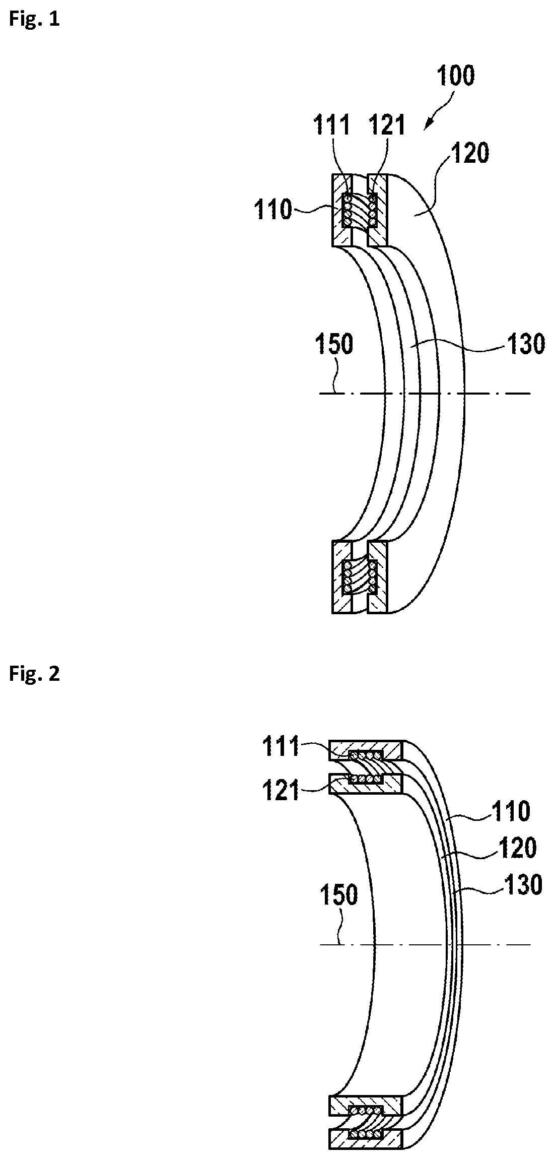
[0030]In FIG. 1, a disk-shaped rotating power transformer 100 is shown. A primary magnetic core 110 having a primary winding 111 is rotatable against a secondary magnetic core 120 having a secondary magnetic winding 121. Between the primary magnetic core 110 and the secondary magnetic core 120 is an air gap 130 in a plane orthogonal to the rotation axis 150.

second embodiment

[0031]In FIG. 2, a drum-shaped rotating power transformer is shown. A primary magnetic core 110 having a primary winding 111 is rotatable against a secondary magnetic core 120 having a secondary magnetic winding 121. Between the primary magnetic core 110 and the secondary magnetic core 120 is an air gap 130 on a cylinder surface coaxial with the rotation axis 150.

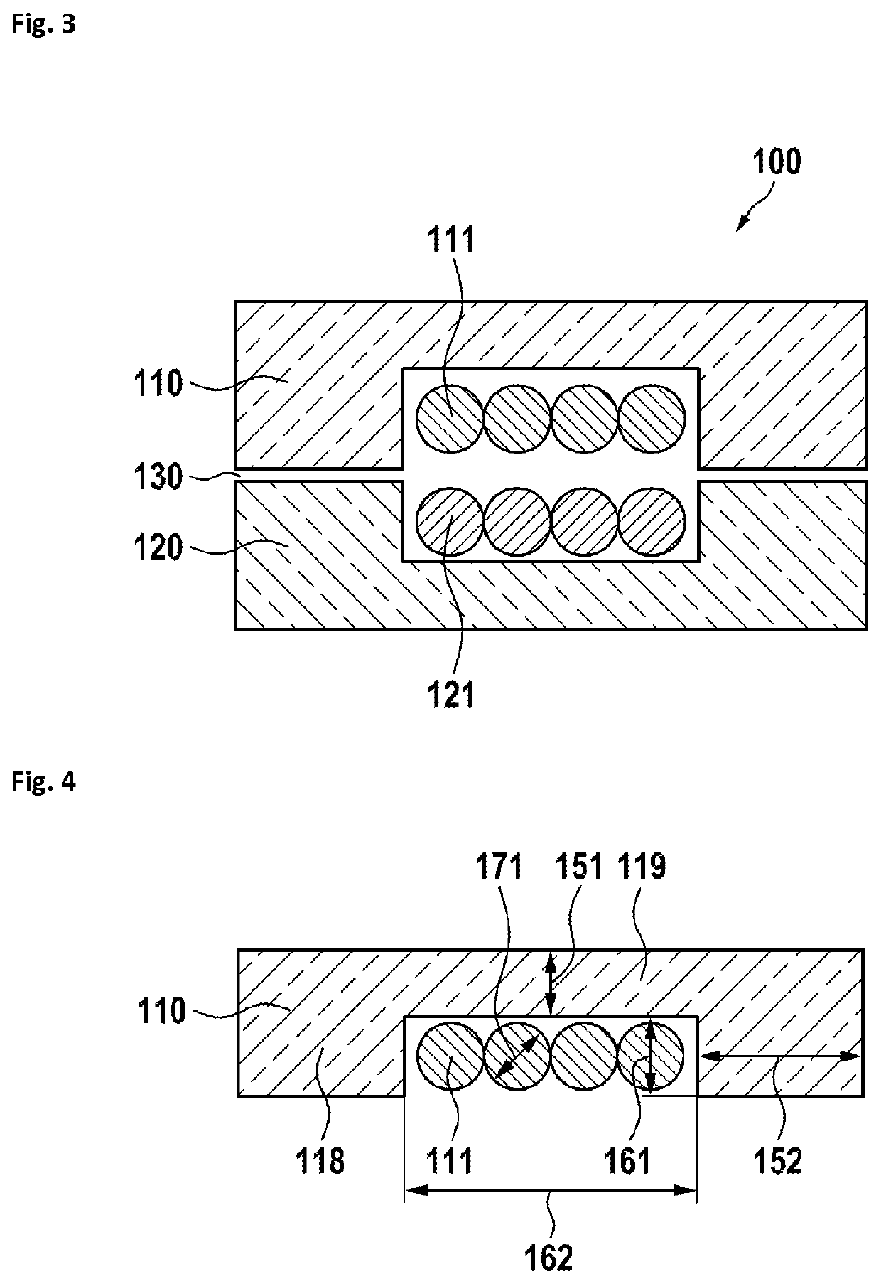
[0032]In FIG. 3, a sectional view of a rotating power transformer is shown.

[0033]A primary magnetic core 110 having a primary winding 111 is rotatable against a secondary magnetic core 120 having a secondary magnetic winding 121. Between the primary magnetic core 110 and the secondary magnetic core 120 is an air gap 130.

[0034]In FIG. 4, dimensions of a magnetic core are shown. The primary magnetic core 110 has essentially the same dimensions as the secondary magnetic core 120. Therefore, reference is only made to the primary magnetic core 110. It has two legs 118 and a base 119 connecting both legs. The legs 118 have a leg ...


PUM

PropertyMeasurementUnit
poweraaaaaaaaaa
bore diameteraaaaaaaaaa
inner diameteraaaaaaaaaa

Abstract

A rotating power transformer comprises a primary magnetic core with a primary winding and a secondary magnetic core with a secondary winding. The magnetic cores preferably comprise a ferrite material and are U-shaped, and have a base connecting two legs. The width of the legs is significantly larger than the height of the base, resulting in a better magnetic coupling and a significantly improved tolerance to mechanical deviations.

Description

CROSS-REFERENCE TO RELATED APPLICATIONS[0001]This application claims priority from and benefit of European Application No. 14198919.4 filed on Dec. 18, 2014, the disclosure of which is incorporated herein by reference.BACKGROUND[0002]Field of the Invention[0003]The invention relates to contactless rotary joints and, specifically, to contactless rotary joints configured to transfer high levels of electrical power, also called rotating power transformers. Such contact-less rotary joints may be used in CT scanners.[0004]Description of Relevant Art[0005]A contactless rotary joint comprising an inductive power coupler is disclosed in U.S. Pat. No. 7,197,113 B1. Such a rotary joint is able to transfer power of more than hundred kilowatts from a stationary part to a rotating part. Such rotary joints have heavy iron or ferrite cores for guiding the magnetic fields. For example, in CT scanners a free bore diameter of more than one meter is required. Accordingly, the inner diameter of such a ...

Claims


Application Information

Patent Timeline
Patent Type & Authority Patents(United States)
IPC IPC(8): H01F21/06H01F21/04H01F38/18A61B6/00H02J50/10H01F27/36H02J5/00H01F27/255H01F27/26H01F27/28A61B6/03
CPCH01F38/18A61B6/56H01F27/255H01F27/263H01F27/2823H01F27/36H02J5/005H02J50/10A61B6/032H01F27/266H01F27/363H02J2310/23
Inventor HERRMANN, ULRICH
Owner SCHLEIFRING GMBH
Why Eureka
Try Eureka