
Generating adapted control instructions for a 3D printing process

a 3d printing and control instruction technology, applied in the direction of additive manufacturing processes, manufacturing data acquisition/processing, design optimisation/simulation, etc., can solve the problems of internal mechanical stresses and deformation of printed objects, unfavorable printing time of a layer, heat trapped inside printed objects, etc., to increase process reliability, accurate follow the top surface, effect of constant pressur

Active Publication Date: 2021-08-17
BOND HIGH PERFORMANCE 3D TECH BV
View PDF6 Cites 0 Cited by
  • Summary
  • Abstract
  • Description
  • Claims
  • Application Information

AI Technical Summary

Benefits of technology

The patent text describes a method to improve the accuracy of printed parts by correcting shrinkage of the material during the printing process and optimizing residual stress and temporary support structures. This is achieved by using simulation results to adapt control instructions, resulting in improved accuracy of the printed shape.

Problems solved by technology

When ME technology is used at realistic speeds however, the printing time of a layer is unfavorable compared to the thermal time constant of the cooling down process.
This causes heat to be trapped inside the printed object.
This may cause internal mechanical stresses and deformation of the printed object.
Thereby inaccurate object shapes may be obtained.
Therefore, heat flows from the area which is printed to the side walls, causing isotherms.
Possible failure during printing may occur when due to the shrinkage and subsequent curving a gap between an object to be manufactured and a print head by which the object is printed becomes too large or too small.
When manufacturing an object by applying a chemical feedstock material such as resins and subsequently curing them, both heat generation, and expansion or shrinkage of the feedstock material while curing may cause deformation of the object, relative to the electronic 3D model.
This change may affect mechanical properties of the 3D object to be manufactured.
Such deformation may lead to further consequences within the ME process.
For example, due to shrinkage as a consequence of temperature change during the ME process, a gap between the nozzle and the previously deposited feedstock material may change unexpectedly.
This may result in further deviations in the actually manufactured 3D object and its mechanical properties in comparison with the result that was expected based on 3D model.
So, by enlarging the electronic 3D model shrinkage can be compensated for, however changes in the abovementioned gap between nozzle and 3D object during printing is not compensated for.
However, parts of the 3D object may deform and lose their intended shape upon cooling down of the 3D object after manufacturing.
Results of this approach however may cause outer object surfaces to be rough due to dithering issues as a result of the deposition of additional compensation layers.

Method used


Image

  • Generating adapted control instructions for a 3D printing process
  • Generating adapted control instructions for a 3D printing process
  • Generating adapted control instructions for a 3D printing process

Examples


Embodiment Construction

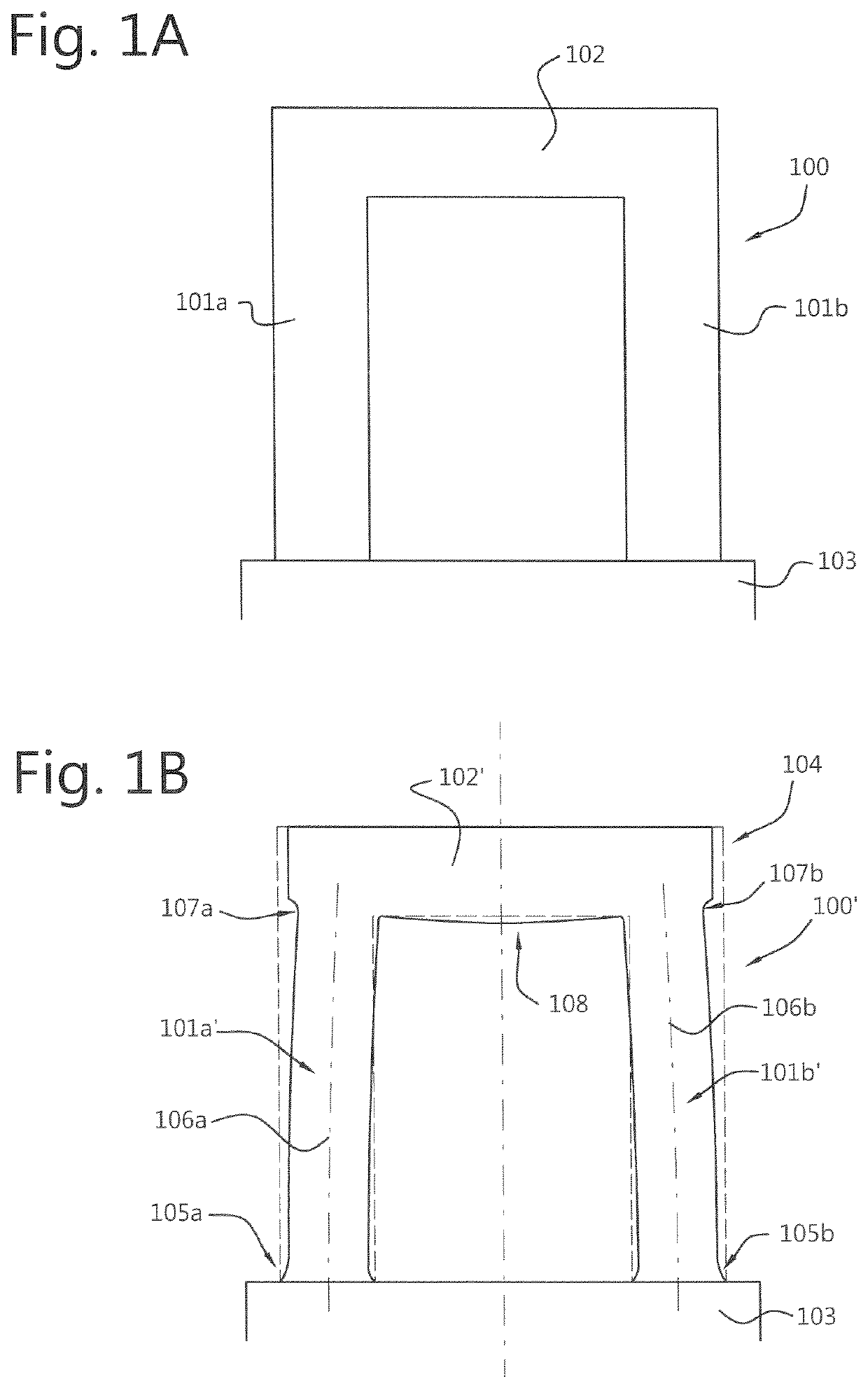
[0101]FIG. 1A shows a two-dimensional (2D) representation of a 3D model of an exemplary 3D object 100 to be manufactured. The 3D object 100 has two upright columns 101a, 101b placed on a base 103, and a crossbar 102 across the tops of the columns. The object 100 can be manufactured according to the state of the art using a 3D printing system using material extrusion (ME).

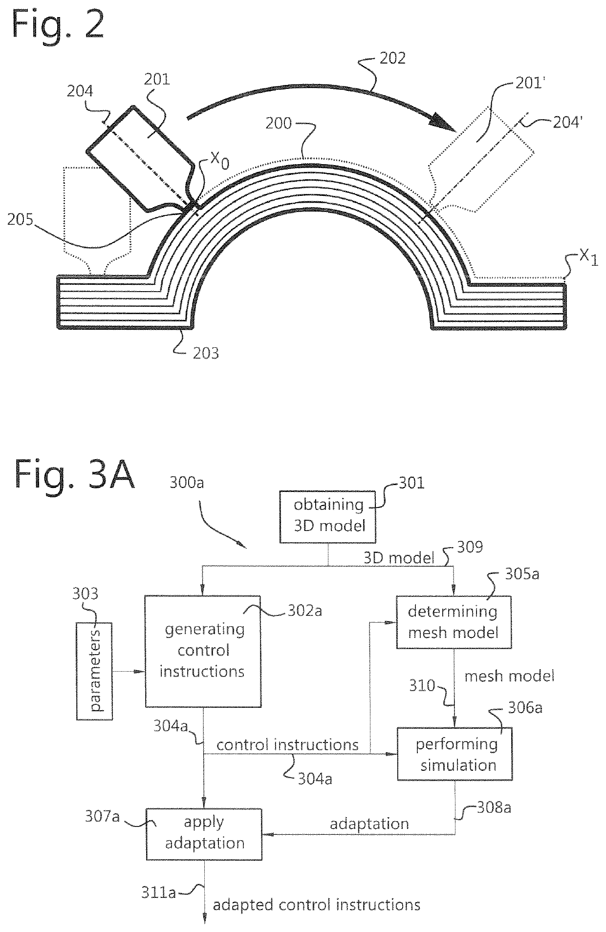
[0102]The ME process according to the state of the art follows the shape of the object 100. When manufactured using the ME system, the printhead is controlled such that it deposits the feedstock material according to electronic toolpaths which in the art are generated using a so-called slicer software tool, wherein a 3D model of the 3D object 100 is translated into slices, i.e. defining layers bottom up of the 3D object, which slices are used to generate electronic toolpaths enabling the ME system to complete the 3D object 100 to be manufactured. When using for example Fused Deposition Modeling (FDM) techniques to m...


PUM

PropertyMeasurementUnit
degrees of freedomaaaaaaaaaa
physical propertyaaaaaaaaaa
temperatureaaaaaaaaaa

Abstract

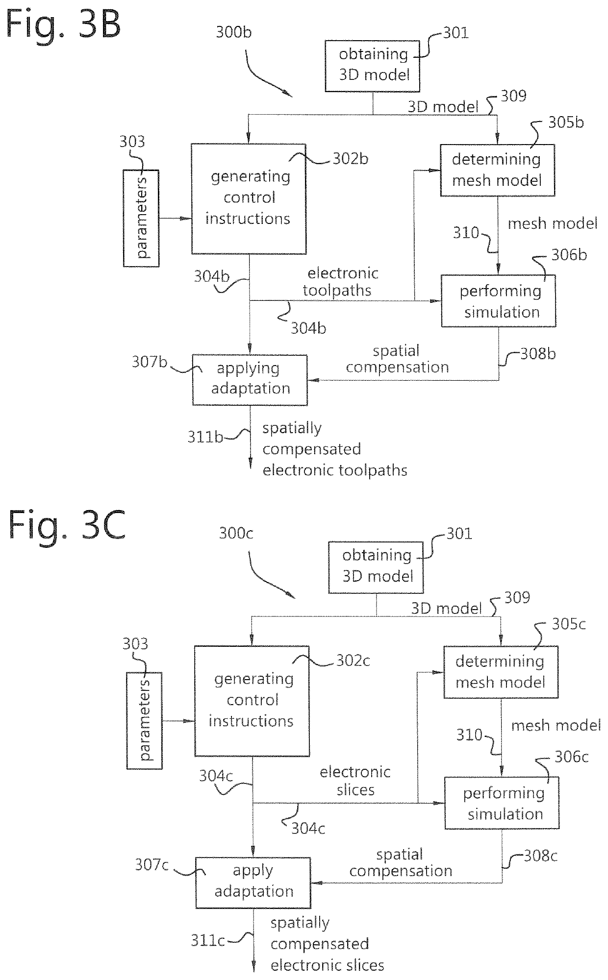
Method and system arranged for obtaining an electronic 3D model of a 3D object to be fabricated. The method further including generating control instructions based on the electronic 3D model and process parameters of the fabrication process, determining a mesh model representing the electronic 3D model, the mesh model including elements each having at least one property that is affectable by at least one of the process parameters, and performing simulation of the fabrication process in time using the control instructions, the mesh model and the process parameters. The simulation includes establishing a deviation of the at least one property relative to a reference thereof for each element of the mesh model, wherein the deviation is induced by at least one of the process parameters, and establishing an adaptation for the at least one property of each element of the mesh model to compensate for the deviation. The adaptation is applied to the process of generating control instructions to obtain at least one adapted control instruction.

Description

FIELD OF THE INVENTION[0001]The invention relates to a method for generating adapted control instructions for a fabrication process of a 3D object using a material extrusion (ME) process for 3D printing. The invention further relates to a fabrication process of a 3D object using a 3D printing ME process. The invention further relates to a system for generating adapted control instructions for a fabrication process of a 3D object using a 3D printing ME process. The invention further relates to a system for fabrication of a 3D object using a 3D printing ME process.BACKGROUND OF THE INVENTION[0002]In 3D modeling, more specifically in 3D printing by material extrusion (ME), objects are formed by layering modeling material in a controlled manner such that a desired three-dimensionally shaped object can be created. Very often for three-dimensional modeling a three-dimensional modeling printer is used. The printer has a three dimensionally moveable printhead which dispenses the modeling ma...

Claims


Application Information

Patent Timeline
Patent Type & Authority Patents(United States)
IPC IPC(8): B29C64/393B33Y50/02B29C64/106G06F30/23G06F30/17
CPCB29C64/393B29C64/106B33Y50/02G06F30/17G06F30/23B33Y10/00B33Y50/00G06F2113/10
Inventor KOOPMANS, NIENKEAZARFAR, ALIREZATROMPER, THIJS
Owner BOND HIGH PERFORMANCE 3D TECH BV
Learn More