Tunable-lens-based refractive examination

a technology of tunable lenses and refractive examination, applied in the field of tunable lenses-based refractive examination, can solve the problems of not being effective for all eye patients, requiring waiting time, and not allowing patients to view through the device, so as to improve the flexibility of patient and clinician use, improve the accuracy of refractive results, and improve the effect of examination speed

Active Publication Date: 2021-08-24
PLENOPTIKA INC
View PDF42 Cites 3 Cited by
  • Summary
  • Abstract
  • Description
  • Claims
  • Application Information

AI Technical Summary

Benefits of technology

[0008]Embodiments described herein can overcome the limitations of existing, separate phoroptry and wavefront aberrometry systems by performing the same functions in the same unit. Furthermore, in many respects, better eye analysis and examination is possible using embodiment apparatuses and methods than is possible with two separate instruments for phoroptry and wavefront aberrometry, whether in a clinical setting or a field-use setting. Example advantages of embodiments include increased examination speed, more accurate refractive results, increased flexibility in patient and clinician use, and the ability to obtain wavefront aberrometry measurements at arbitrary times during phoroptry and accommodation measurements. Moreover, embodiments including portable apparatuses can even be configured to perform lensometry measurements. Embodiment apparatuses and methods can also provide patients with an indication of how their vision will improve with lenses having ref...

Problems solved by technology

First, they do not allow a patient to view through the device so that the patient's eyes can automatically tend toward a relaxed, unaccommodated state.
However, this treatment includes side effects and requires waiting time between treatment and aberrometry measurements.
However, this approach also has limitations and is not effective for all eye patients.
Furthermore, existing portable wavefront aberrometers (i) do not provide phoroptry measurements, which take into account a patient's subjective preference, which is typically slightly different from the correction indicated by purely objectiv...

Method used


Image

  • Tunable-lens-based refractive examination
  • Tunable-lens-based refractive examination
  • Tunable-lens-based refractive examination

Examples


Embodiment Construction

[0048]A description of example embodiments of the invention follows.

[0049]Refractive eye examinations by an optometrist or ophthalmologist typically involve using a phoropter to determine which of many fixed lens settings produces the best eyesight, subjectively, for a given patient. Clinical phoropters are usually binocular (enabling both of a patient's eyes to view through separate sets of lenses) and open-view (enabling a patient to view, through the phoropter lenses, a distant target pattern). Typically, the patient is asked to focus on a target pattern situated a distance of about 20 feet from the patient's eye. The open-view design also performs the important function of encouraging the patient's eyes to remain unaccommodated (relaxed and as optimized as possible for long-distance viewing) during the measurement. The unaccommodated state is an important clinical prerequisite for accurate measurements for refractive correction of distance vision. Thus, using typical clinical ph...


PUM


Abstract

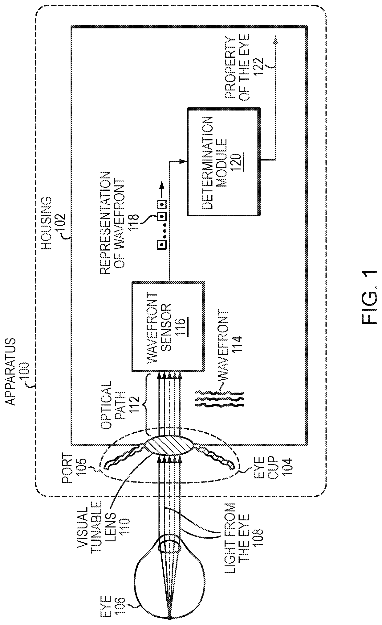
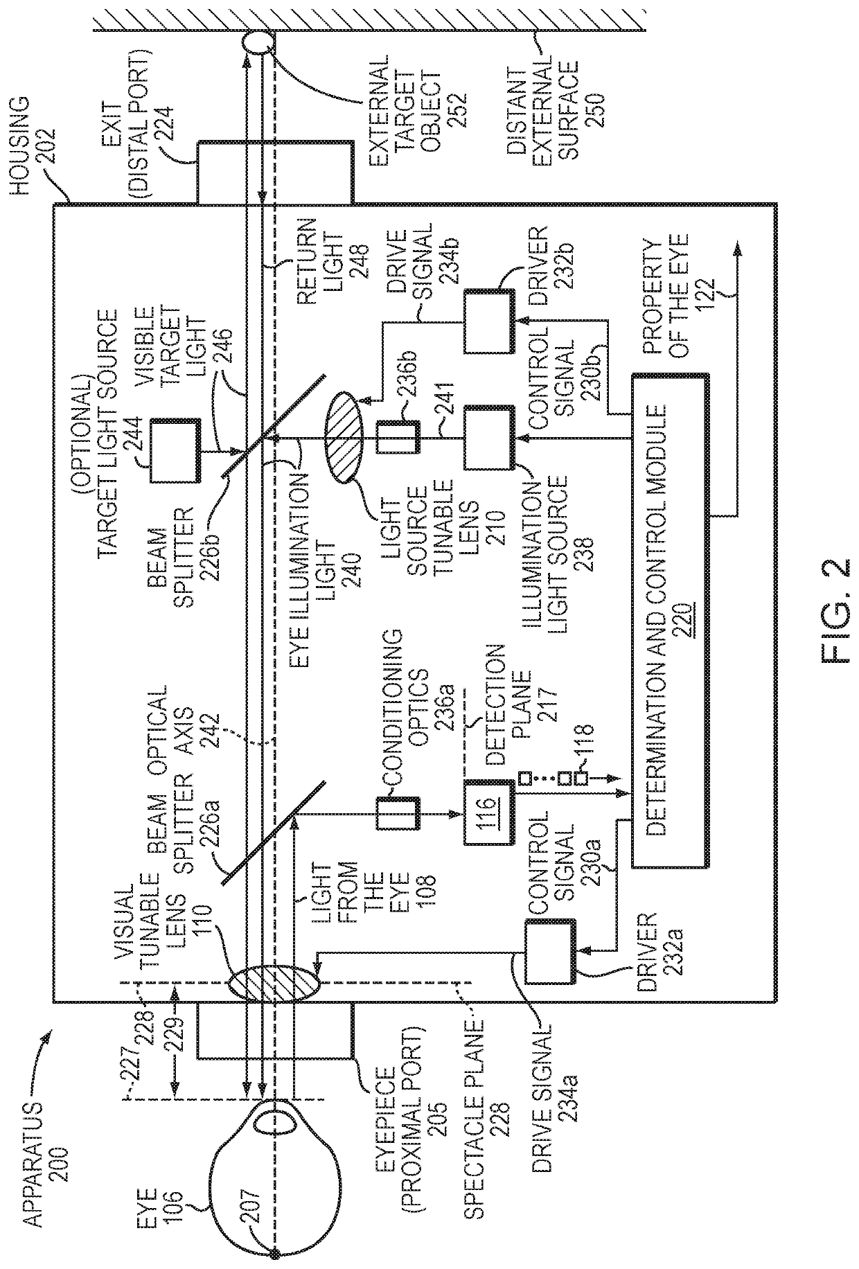
An apparatus, and corresponding method, for determining a refractive property of an eye includes a housing with a port configured to receive an eye and also light from the eye. A tunable lens can be mounted to the housing to apply a variable focal power to the light from the eye and to pass the light along an optical path toward a wavefront sensor within the housing. The wavefront sensor can receive the light via the optical path and measure a wavefront thereof. A determination module can be configured to determine a property of the eye based on the wavefront. Embodiments can be handheld, portable, and open view, while providing objective wavefront aberrometry, subjective phoroptry, and accommodation and presbyoptic evaluation, as well as lensometry functions.

Description

RELATED APPLICATIONS[0001]This application is the U.S. National Stage of International Application No. PCT / US2017 / 037257, filed Jun. 13, 2017, which designates the U.S., published in English, and claims the benefit of U.S. Provisional Application No. 62 / 350,018, filed on Jun. 14, 2016. The entire teachings of the above Applications are incorporated herein by reference.GOVERNMENT SUPPORT[0002]This invention was made with government support under SBIR 1R43EY025452-01A1 and SBIR 2R44EY025452-02A1 from the National Eye Institute of the National Institutes of Health. The government has certain rights in the invention.BACKGROUND[0003]Optometrists or ophthalmologists performing eye examinations in a clinic typically use a phoropter (or equivalently, a trial lens set) to determine which of many fixed lens settings produces the best eyesight, subjectively, for a given patient. However, this is a lengthy process due to the iterative nature of the subjective refraction. To speed up the process...

Claims


Application Information

Patent Timeline
IPC IPC(8): A61B3/18A61B3/00A61B3/09A61B3/103A61B3/12A61B3/028
CPCA61B3/18A61B3/005A61B3/0008A61B3/0033A61B3/028A61B3/0285A61B3/09A61B3/103A61B3/1208A61B3/1015A61B3/10
Inventor DAVE, SHIVANG R.LIM, DARYLDURR, NICHOLAS JAMES
Owner PLENOPTIKA INC
Why Eureka
Try Eureka