Control valve

a control valve and valve body technology, applied in the direction of valve operating means/release devices, machines/engines, transportation and packaging, etc., can solve the problems of bending deformation and gap formation achieve the effect of enhancing the sealing between the seal cylindrical member and the valve body, easy setting and regulation, and reducing the risk of bending

Active Publication Date: 2021-08-31
YAMADA MANUFACTURING CO LTD
View PDF16 Cites 1 Cited by
  • Summary
  • Abstract
  • Description
  • Claims
  • Application Information

AI Technical Summary

Benefits of technology

[0008]An aspect according to the present invention has been made in consideration of such circumstances, and an objective of the present invention is to provide a control valve capable of alleviating variation in bending in the circumferential direction of the seal cylindrical member due to change in the protrusion height of the end portion in the axial direction of the seal cylindrical member and enhancing sealing between the seal cylindrical member and the valve body.
[0013]In the case of the above-described aspect (2), a pressure of the liquid inside the casing that acts from the radial outer side of the seal cylindrical member can be efficiently received by the radial inner side of the seal cylindrical member. Therefore, when the above-described aspect (2) is employed, variation in the bending in the circumferential direction of the seal cylindrical member can be more stably alleviated.
[0015]In the case of the above-described aspect (3), variation in surface pressure in the circumferential direction of the valve sliding contact surface can also be alleviated while variation in bending in the circumferential direction of the seal cylindrical member can be alleviated by the thick portion. Therefore, when this configuration is employed, sealing between the valve sliding contact surface of the seal cylindrical member and the circumferential wall portion of the valve body can be further enhanced.
[0017]In the case of the above-described aspect (4), since a pair of linear inner edge portions parallel to the rotation axis of the valve body are provided on the valve sliding contact surface by the thick portions, when the other end portion of the seal cylindrical member communicates with the valve hole of the valve body according to rotation of the valve body, it communicates initially with the valve hole at one of the linear inner edge portions. Also, when the other end portion of the seal cylindrical member is no longer able to communicate with the valve hole of the valve body due to rotation in the same direction of the valve body, it finally communicates with the valve hole at the other of the linear inner edge portions. In the above-described aspect (4), since the linear inner edge portions parallel to the rotation axis of the valve body are provided on the valve sliding contact surface, a fixed communication start position and communication end position of the valve hole can be maintained due to the linear inner edge portions. Therefore, when the above-described aspect (4) is employed, outflow characteristics of a liquid can be made stable.
[0019]In the case of the above-described aspect (5), a flow rate of a liquid flowing out to a downstream side of the outlet through the seal cylindrical member is determined by the inner diameter of the first cylindrical portion of the seal cylindrical member having a relatively small inner diameter. Since the thick portion is provided on the radial inner side of the second cylindrical portion having a relatively large inner diameter, the thick portion does not affect the flow rate of the liquid flowing out to the downstream side of the outlet. Therefore, when the above-described aspect (5) is employed, a flow rate of a liquid flowing out to the outlet can be easily set and regulated.
[0020]In the aspect according to the present invention, the thick portion which is thicker compared to other portions is provided in a region in which the protrusion height is high on the circumferential wall of the other end portion in the axial direction of the seal cylindrical member, and thereby a region which is likely to cause bending deformation is reinforced by the thick portion. Therefore, according to the aspect of the present invention, variation in bending in the circumferential direction of the seal cylindrical member due to change in the protrusion height of the end portion in the axial direction of the seal cylindrical member can be alleviated. Therefore, when the aspect according to the present invention is employed, sealing between the seal cylindrical member and the valve body can be enhanced.

Problems solved by technology

However, since the protrusion height of the other end portion of the seal cylindrical member continuously changes to follow an outer surface shape of the valve body in the above-described conventional control valve, bending deformation is likely to occur in a region at which the protrusion height of the other end portion of the seal cylindrical member is high when a fluid pressure inside the casing is received from the outside in the radial direction.
Therefore, variation may occur in a degree of ease with which the seal cylindrical member is bent in the circumferential direction due to change in the protrusion height at an end portion in the axial direction of the seal cylindrical member, and as a result, there is a concern that a gap may be formed between the seal cylindrical member and the valve body.

Method used


Image

  • Control valve
  • Control valve
  • Control valve

Examples


Embodiment Construction

[0032]Next, an embodiment of the present invention will be described on the basis of the drawings. In the following description, a case in which a control valve of the present embodiment is employed in a cooling system for cooling an engine using cooling water will be described. In each embodiment, the same parts are denoted by the same references and duplicated descriptions thereof will be omitted.

[0033][Cooling System]

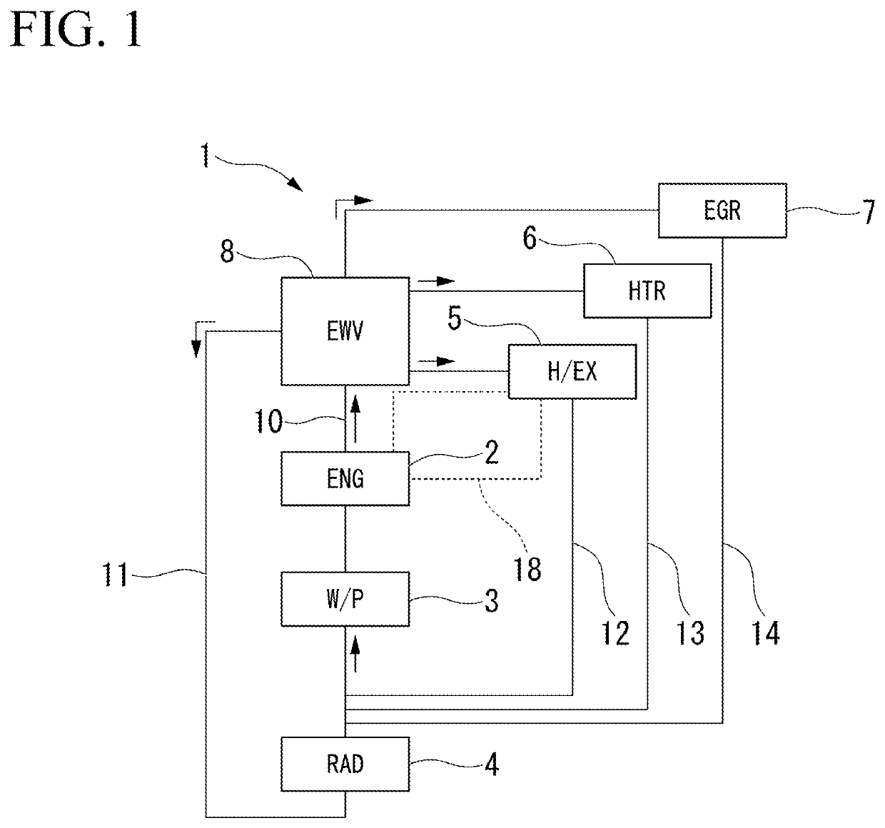
[0034]FIG. 1 is a block diagram of a cooling system 1.

[0035]As illustrated in FIG. 1, the cooling system 1 is mounted on a vehicle in which at least an engine is included as a vehicle drive source. As a vehicle, a hybrid vehicle, a plug-in hybrid vehicle, or the like may be included in addition to a vehicle having only an engine.

[0036]The cooling system 1 is configured such that an engine 2 (ENG), a water pump 3 (W / P), a radiator 4 (RAD), a heat exchanger 5 (H / EX), a heater core 6 (HTR), an EGR cooler 7 (EGR), and a control valve 8 (EWV) are connected by various flow...


PUM


Abstract

A control valve includes a casing, a valve body, and a seal cylindrical member. The casing includes an inlet and an outlet. The valve body is rotatably disposed inside the casing and includes a circumferential wall portion in which a valve hole that allows the inside and outside to communicate is formed. The seal cylindrical member includes one end portion which communicates with a downstream side of an outlet and the other end portion on which a valve sliding contact surface is provided. In the other end portion of the seal cylindrical member, a protrusion height changes continuously in a circumferential direction along a shape of an outer circumferential surface of the circumferential wall portion. A thick portion which is thicker compared to other portions is provided in a region of the other end portion of the seal cylindrical member at which the protrusion height is high.

Description

CROSS-REFERENCE TO RELATED APPLICATION[0001]Priority is claimed on Japanese Patent Application No. 2018-171893, filed Sep. 13, 2018, the content of which is incorporated herein by reference.BACKGROUND OF THE INVENTIONField of the Invention[0002]The present invention relates to a control valve used for switching a flow path of cooling water for vehicles.Description of Related Art[0003]In cooling systems that cool engines using cooling water, there are cases in which a bypass flow path that bypasses a radiator, a warmer fluid flow path through which an oil warmer passes, and the like are provided in combination in addition to a radiator flow path for circulation between the radiator and the engine. In this type of cooling system, a control valve is interposed at a branch portion of flow paths, and the flow paths are switched by the control valve as appropriate. As a control valve, one in which a valve body having a cylindrical shape is rotatably disposed inside a casing and an arbitra...

Claims


Application Information

Patent Timeline
Patent Type & Authority Patents(United States)
IPC IPC(8): F16K11/08F16K5/18F01P7/14F16K25/00F16K11/02F16K5/04F16K31/00B60H1/00
CPCF16K11/022F01P7/14F16K5/0428B60H1/00885F01P2007/146F16K31/005Y10T137/86533F16K11/0856F01P2050/24F01P2050/22F16K11/085F16K5/0464F16K5/181F01P7/165F01P2060/08F01P2060/16F01P2060/04F16K25/00
Inventor OZEKI, AKIFUMI
Owner YAMADA MANUFACTURING CO LTD
Why Eureka
Try Eureka